PART IDENTIFICATION CHART
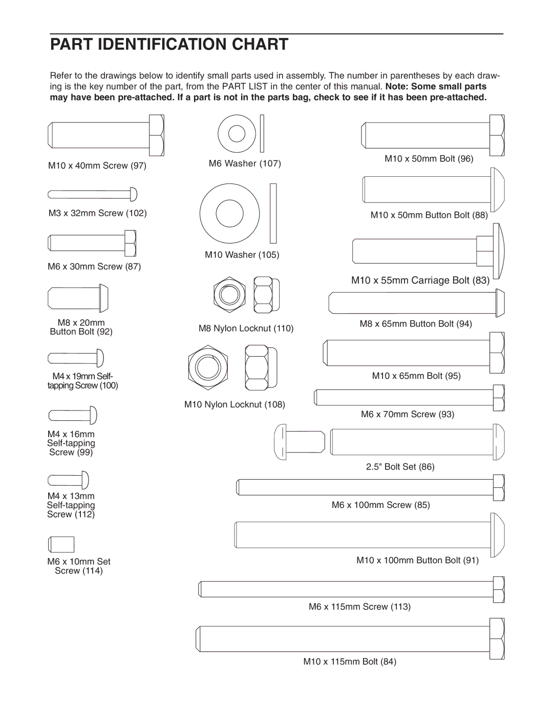
Refer to the drawings below to identify small parts used in assembly. The number in parentheses by each draw- ing is the key number of the part, from the PART LIST in the center of this manual. Note: Some small parts may have been
M10 x 40mm Screw (97)
M3 x 32mm Screw (102)
M6 x 30mm Screw (87)
M8 x 20mm
Button Bolt (92)
M4 x 19mm Self-
tapping Screw (100)
M4 x 16mm
Screw (99)
M6 Washer (107)
M10 Washer (105)
M8 Nylon Locknut (110)
M10 Nylon Locknut (108)
M10 x 50mm Bolt (96)
M10 x 50mm Button Bolt (88)
M10 x 55mm Carriage Bolt (83)
M8 x 65mm Button Bolt (94)
M10 x 65mm Bolt (95)
M6 x 70mm Screw (93)
2.5" Bolt Set (86)
M4 x 13mm
Screw (112)
M6 x 100mm Screw (85)
M6 x 10mm Set | M10 x 100mm Button Bolt (91) |
|
| ||
Screw (114) |
|
|
|
| |
|
|
|
|
|
|
|
|
|
|
|
|
|
|
|
|
|
|
|
| M6 x 115mm Screw (113) |
|
| |
|
|
|
|
|
|
|
|
|
|
|
|
|
|
|
|
|
|
|
|
|
|
|
|
M10 x 115mm Bolt (84)