WEIGHT RESISTANCE CHART
The chart below shows the approximate weight resistance for the 12.5 lb. weights. Note: The actual resistance at each station may vary due to differences in individual weight plates and friction between the cables, pulleys, and weight guides.
WEIGHT | 1 | 2 | 3 | 4 | 5 | 6 | 7 | 8 | 9 | 10 | 11 | 12 | |
|
|
|
|
|
|
|
|
|
|
|
|
| |
Press | 9 | 15 | 20 | 25 | 30 | 36 | 41 | 46 | 51 | 57 | 62 | 67 | |
Arm* | |||||||||||||
|
|
|
|
|
|
|
|
|
|
|
| ||
|
|
|
|
|
|
|
|
|
|
|
|
| |
Leg | 20 | 30 | 42 | 50 | 65 | 73 | 92 | 97 | 108 | 125 | 137 | 144 | |
Developer | |||||||||||||
|
|
|
|
|
|
|
|
|
|
|
| ||
|
|
|
|
|
|
|
|
|
|
|
|
|
*The weight resistance shown is for each arm.
CABLE DIAGRAM
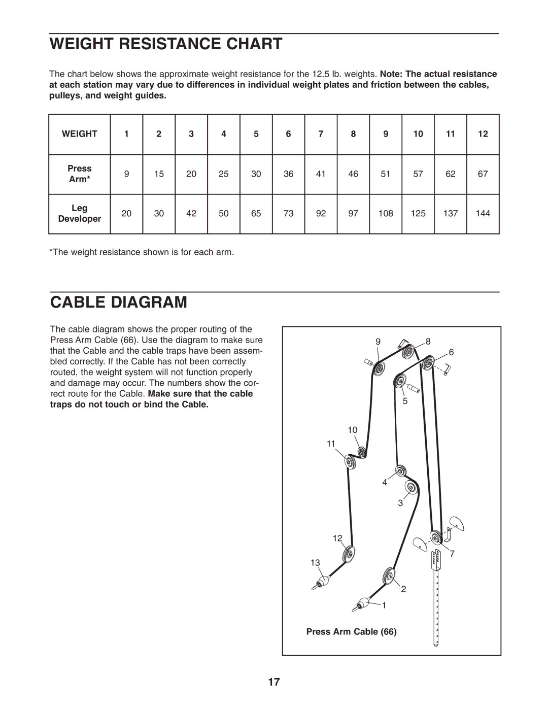
The cable diagram shows the proper routing of the Press Arm Cable (66). Use the diagram to make sure that the Cable and the cable traps have been assem- bled correctly. If the Cable has not been correctly routed, the weight system will not function properly and damage may occur. The numbers show the cor- rect route for the Cable. Make sure that the cable traps do not touch or bind the Cable.
9 | 8 |
| 6 |
| 5 |
10 |
|
11 |
|
4 |
|
| 3 |
12 |
|
13 | 7 |
| |
| 2 |
1 |
|
Press Arm Cable (66) |
|
17