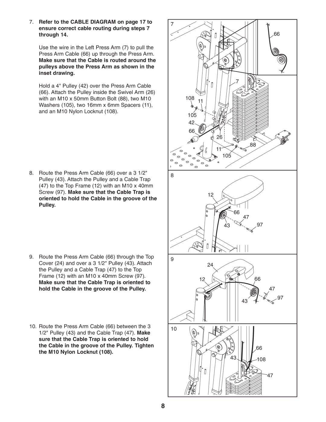
7. | Refer to the CABLE DIAGRAM on page 17 to | 7 |
|
|
|
| ensure correct cable routing during steps 7 |
|
|
| |
|
|
|
| 66 | |
| through 14. |
|
|
| |
| Use the wire in the Left Press Arm (7) to pull the |
|
|
|
|
| Press Arm Cable (66) up through the Press Arm. |
|
|
|
|
| Make sure that the Cable is routed around the |
|
|
|
|
| pulleys above the Press Arm as shown in the |
|
|
|
|
| inset drawing. |
|
|
|
|
| Hold a 4" Pulley (42) over the Press Arm Cable |
| 7 |
|
|
|
|
|
|
| |
| (66). Attach the Pulley inside the Swivel Arm (26) | 108 |
|
|
|
| with an M10 x 50mm Button Bolt (88), two M10 | 11 |
|
| |
| Washers (105), two 16mm x 6mm Spacers (11), |
|
|
|
|
| and an M10 Nylon Locknut (108). | 105 |
|
|
|
|
|
|
|
| |
|
| 42 |
|
|
|
|
| 66 |
|
|
|
|
|
| 26 |
|
|
|
|
| 11 |
| 88 |
|
|
|
|
| |
|
|
| 105 |
|
|
8. | Route the Press Arm Cable (66) over a 3 1/2" | 8 |
|
|
|
| Pulley (43). Attach the Pulley and a Cable Trap |
|
|
| |
|
|
|
|
| |
| (47) to the Top Frame (12) with an M10 x 40mm |
|
|
|
|
| Screw (97). Make sure that the Cable Trap is |
| 12 |
|
|
| oriented to hold the Cable in the groove of the |
|
|
| |
|
|
|
|
| |
| Pulley. |
|
|
|
|
|
|
| 66 | 47 |
|
|
|
|
|
| |
|
|
| 43 |
| 97 |
9. | Route the Press Arm Cable (66) through the Top | 9 |
|
|
|
| Cover (24) and over a 3 1/2" Pulley (43). Attach | 24 |
|
| |
|
|
|
| ||
| the Pulley and a Cable Trap (47) to the Top |
|
|
| |
|
|
|
|
| |
| Frame (12) with an M10 x 40mm Screw (97). |
| 12 |
| 66 |
| Make sure that the Cable Trap is oriented to |
|
| ||
|
|
|
|
| |
| hold the Cable in the groove of the Pulley. |
|
|
| 47 |
|
|
|
| 43 | 97 |
|
|
|
|
| |
10. | Route the Press Arm Cable (66) between the 3 | 10 |
|
|
|
| 1/2" Pulley (43) and the Cable Trap (47). Make |
|
|
| |
|
|
|
|
| |
| sure that the Cable Trap is oriented to hold |
|
|
|
|
| the Cable in the groove of the Pulley. Tighten |
|
|
| 66 |
| the M10 Nylon Locknut (108). |
|
|
| |
|
| 43 |
|
| |
|
|
|
| 108 | |
|
|
|
|
| |
|
|
|
|
| 47 |
|
| 8 |
|
|
|