secure them by partially tightening the two screw clamps built into the Base assembly.
6.Set the Arm (118) assembly column into the Column Base. Move the Arm slightly to the left or right until the column index knob locks into the arm support column.
The arm support column has nine positive stops: 0, 15, 30, 45, and 60° (left and right).
7.Attach the Elevating Handle assem- bly to the Arm using the Allen wrench (provided).
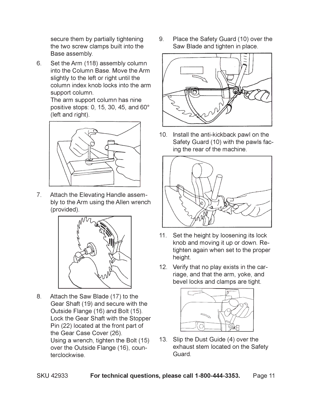
8.Attach the Saw Blade (17) to the Gear Shaft (19) and secure with the Outside Flange (16) and Bolt (15). Lock the Gear Shaft with the Stopper Pin (22) located at the front part of the Gear Case Cover (26).
Using a wrench, tighten the Bolt (15) over the Outside Flange (16), coun- terclockwise.
9.Place the Safety Guard (10) over the Saw Blade and tighten in place.
10.Install the
11.Set the height by loosening its lock knob and moving it up or down. Re- tighten again when set to the proper height.
12.Verify that no play exists in the car- riage, and that the arm, yoke, and bevel locks and clamps are tight.
13.Slip the Dust Guide (4) over the exhaust stem located on the Safety Guard.
SKU 42933 | For technical questions, please call | Page 11 |