Instructions for putting
into use
Read the entire Important Safety Information section at the beginning of this manual including all text under subheadings therein before set up or use of this product.
To prevent serious injury
from accidental operation:
Release the Trigger and unplug the tool from its electrical outlet before assembling or making any adjustments to the tool.
Note: For additional information regarding the parts listed in the following pages, refer to the Assembly Diagram near the end of this manual.
Assembly
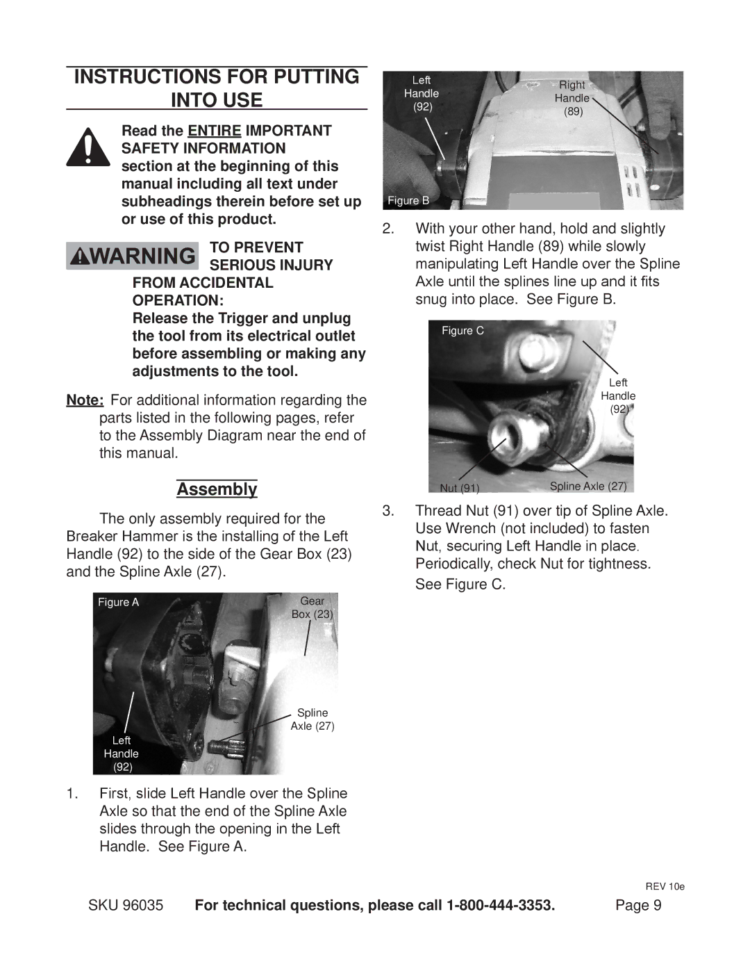
The only assembly required for the Breaker Hammer is the installing of the Left Handle (92) to the side of the Gear Box (23) and the Spline Axle (27).
Figure A | Gear |
| Box (23) |
Spline
Axle (27)
Left
Handle (92)
1.First, slide Left Handle over the Spline
Axle so that the end of the Spline Axle slides through the opening in the Left
Handle. See Figure A.
Left | Right | |
Handle | ||
Handle | ||
(92) | ||
(89) | ||
|
Figure B
2.With your other hand, hold and slightly twist Right Handle (89) while slowly manipulating Left Handle over the Spline Axle until the splines line up and it fits snug into place. See Figure B.
Figure C
Left
Handle (92)
Nut (91) | Spline Axle (27) |
3.Thread Nut (91) over tip of Spline Axle. Use Wrench (not included) to fasten
Nut, securing Left Handle in place.
Periodically, check Nut for tightness. See Figure C.
REV 10e
SKU 96035 | For technical questions, please call | Page 9 |
