Section 2 - Installation
A - Handling
The CPVS Compressor must always be handled with care. It may be lifted either with a forklift truck or by means of a travelling crane. In the latter case, precautions must be taken so as not to damage the unit's cowling.
B - Room
The CPVS is designed to operate in a
(see page 2).
If operating the compressor causes the ambient temperature to rise above 104 °F, the warm air leaving the radiator must be discharge outside.
COMMENT
When the atmosphere is contaminated by organic or mineral dust or by corrosive chemical emanations the following precautions must be taken:
1.Provide another air inlet as close as possible to the compressor suction.
2.Use an additional filter. (see options Section 5), on the machine's ventilation intakes.
Installation with heat dispersion sleeve
If the operation of the compressor increases the ambient temperature above 104 °F, it is necessary to discharge the hot air leaving the radiator to the exterior by means of the sleeve.
Prevailing wind
| V |
L | Flexible fitting |
|
Compressor
Fig. 2a - Sleeve with roof outlet
|
|
| d |
|
| ||
|
|
|
|
|
|
|
|
|
|
|
|
|
|
|
|
|
|
|
|
|
|
|
|
L |
|
|
| Ventilation | Duct minimum cross section | ||
|
|
|
|
|
| flow rate | ( d ≤ L ≤ 1,6d ) |
|
|
|
|
|
| cfm | sqf |
|
|
|
|
|
| ||
CPVS 40 | 2860 | 2.6 | |||||
|
|
|
|
|
|
|
|
CPVS 50 | 2860 | 2.6 | |||||
CPVS 60 | 3920 | 3.6 | |||||
CPVS 75 | 5300 | 4.9 | |||||
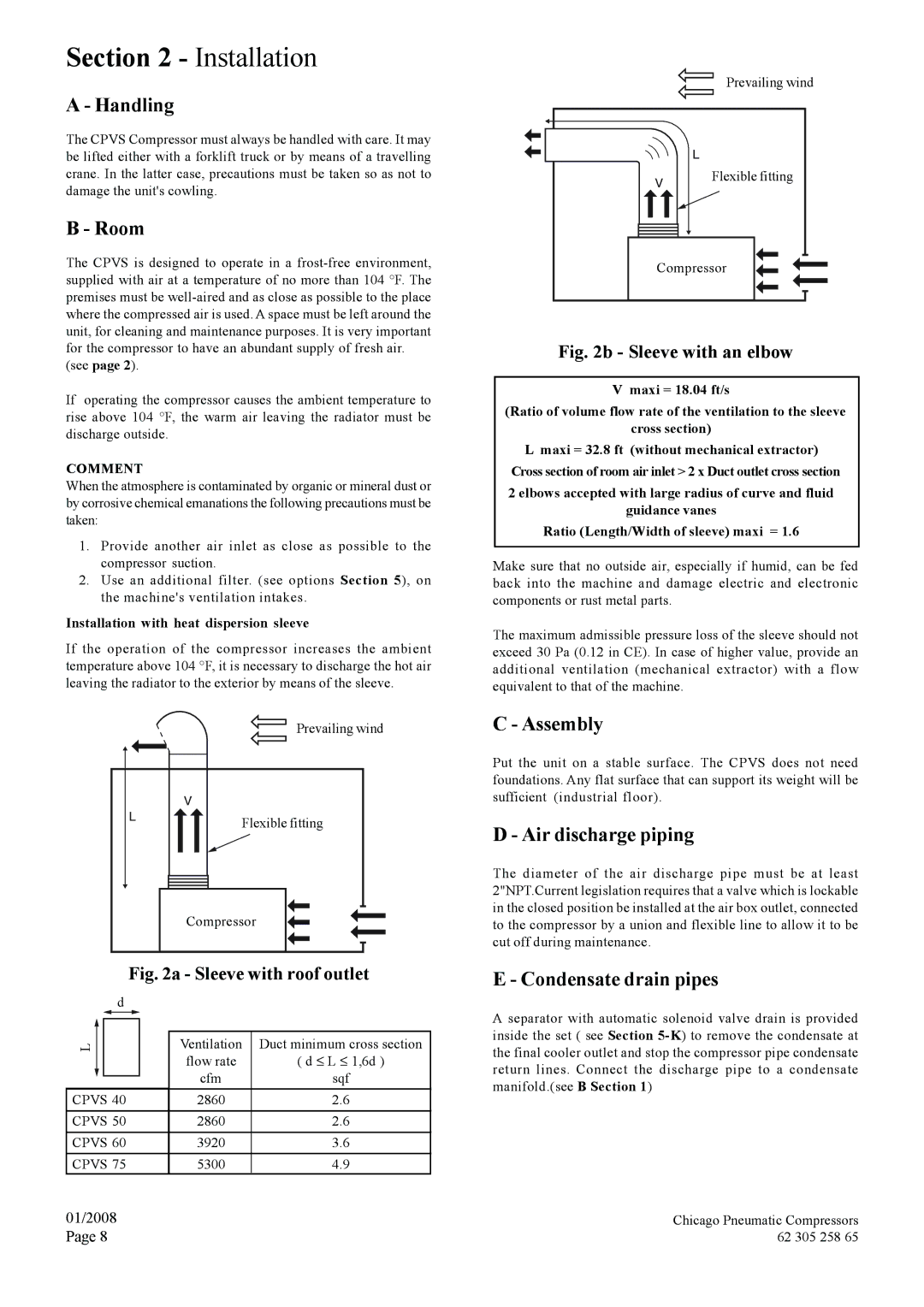
Prevailing wind
| L |
V | Flexible fitting |
| |
Compressor | |
Fig. 2b - Sleeve with an elbow
V maxi = 18.04 ft/s
(Ratio of volume flow rate of the ventilation to the sleeve cross section)
Lmaxi = 32.8 ft (without mechanical extractor) Cross section of room air inlet > 2 x Duct outlet cross section
2 elbows accepted with large radius of curve and fluid
guidance vanes
Ratio (Length/Width of sleeve) maxi = 1.6
Make sure that no outside air, especially if humid, can be fed back into the machine and damage electric and electronic components or rust metal parts.
The maximum admissible pressure loss of the sleeve should not exceed 30 Pa (0.12 in CE). In case of higher value, provide an additional ventilation (mechanical extractor) with a flow equivalent to that of the machine.
C - Assembly
Put the unit on a stable surface. The CPVS does not need foundations. Any flat surface that can support its weight will be sufficient (industrial floor).
D - Air discharge piping
The diameter of the air discharge pipe must be at least 2"NPT.Current legislation requires that a valve which is lockable in the closed position be installed at the air box outlet, connected to the compressor by a union and flexible line to allow it to be cut off during maintenance.
E - Condensate drain pipes
A separator with automatic solenoid valve drain is provided inside the set ( see Section
01/2008 | Chicago Pneumatic Compressors |
Page 8 | 62 305 258 65 |