CM2C40 | Installation Instructions |
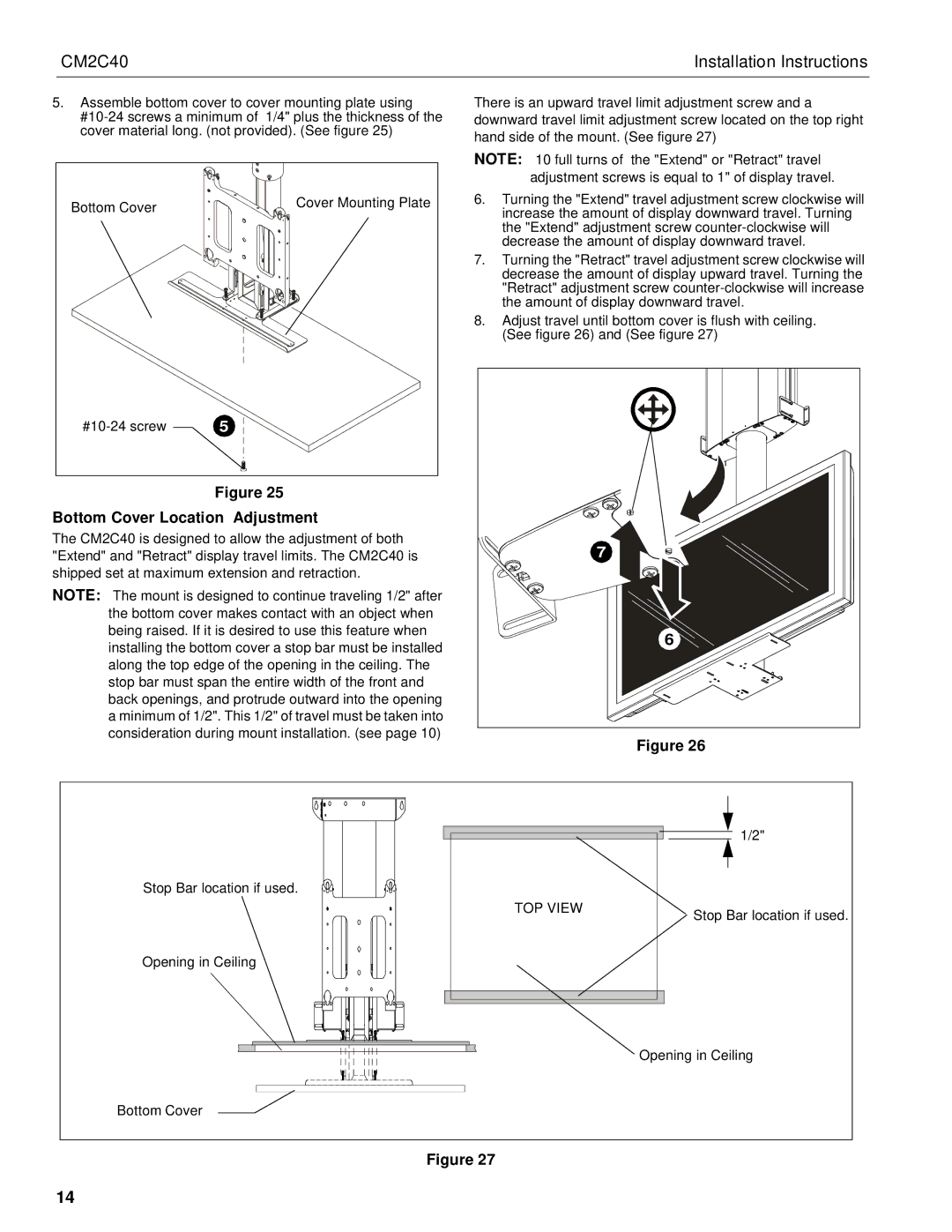
5.Assemble bottom cover to cover mounting plate using
Bottom Cover | Cover Mounting Plate |
| |
5 |
Figure 25
Bottom Cover Location Adjustment
The CM2C40 is designed to allow the adjustment of both "Extend" and "Retract" display travel limits. The CM2C40 is shipped set at maximum extension and retraction.
NOTE: The mount is designed to continue traveling 1/2" after the bottom cover makes contact with an object when being raised. If it is desired to use this feature when installing the bottom cover a stop bar must be installed along the top edge of the opening in the ceiling. The stop bar must span the entire width of the front and back openings, and protrude outward into the opening a minimum of 1/2". This 1/2" of travel must be taken into consideration during mount installation. (see page 10)
There is an upward travel limit adjustment screw and a downward travel limit adjustment screw located on the top right hand side of the mount. (See figure 27)
NOTE: 10 full turns of the "Extend" or "Retract" travel adjustment screws is equal to 1" of display travel.
6.Turning the "Extend" travel adjustment screw clockwise will increase the amount of display downward travel. Turning the "Extend" adjustment screw
7.Turning the "Retract" travel adjustment screw clockwise will decrease the amount of display upward travel. Turning the "Retract" adjustment screw
8.Adjust travel until bottom cover is flush with ceiling. (See figure 26) and (See figure 27)
7 |
6 |
Figure 26
Stop Bar location if used.
TOP VIEW
1/2"
![]() Stop Bar location if used.
Stop Bar location if used.
Opening in Ceiling
Opening in Ceiling
Bottom Cover
Figure 27
14