CM2C40 |
|
| Installation Instructions | ||
6 |
|
|
|
| |
10 |
|
|
|
| |
10 |
|
|
|
| |
6 |
|
|
|
| |
|
|
| 9 | x2 | |
|
|
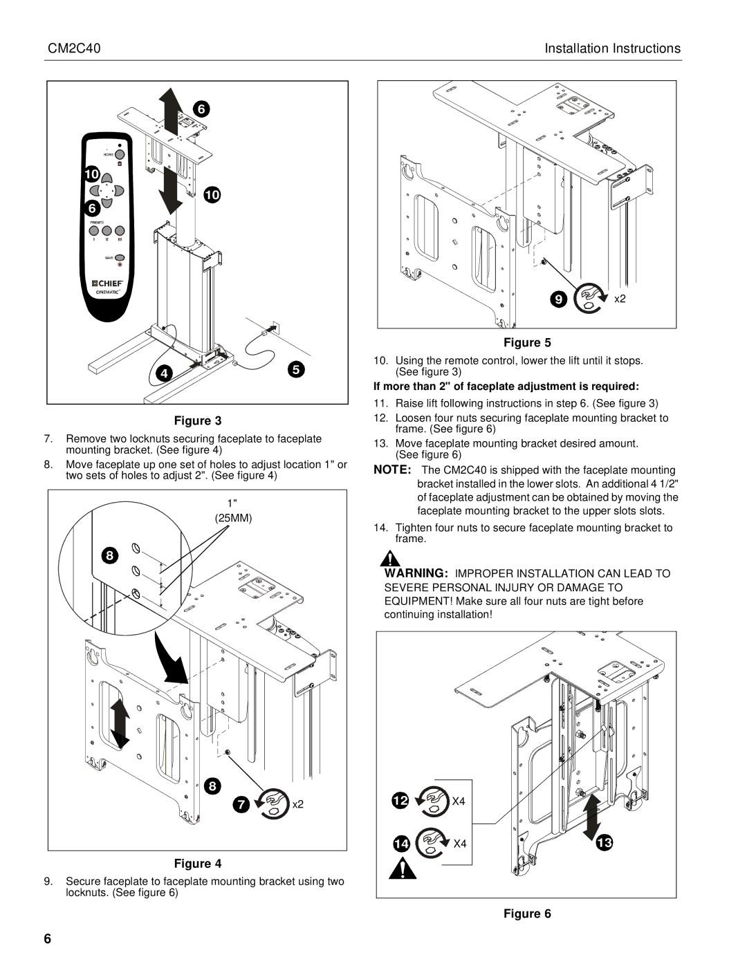
| Figure 5 |
| |
| 5 | 10. Using the remote control, lower the lift until it stops. | |||
4 | (See figure 3) |
| |||
|
| If more than 2" of faceplate adjustment is required: | |||
|
| 11. Raise lift following instructions in step 6. (See figure 3) | |||
Figure 3 |
| 12. Loosen four nuts securing faceplate mounting bracket to | |||
7. Remove two locknuts securing faceplate to faceplate | frame. (See figure 6) |
| |||
13. Move faceplate mounting bracket desired amount. | |||||
mounting bracket. (See figure 4) |
| ||||
| (See figure 6) |
| |||
8. Move faceplate up one set of holes to adjust location 1" or |
| ||||
NOTE: The CM2C40 is shipped with the faceplate mounting | |||||
two sets of holes to adjust 2". (See figure 4) |
| ||||
|
| bracket installed in the lower slots. An additional 4 1/2" | |||
|
|
| |||
1" |
|
| of faceplate adjustment can be obtained by moving the | ||
|
| faceplate mounting bracket to the upper slots slots. | |||
(25MM) |
|
| |||
| 14. Tighten four nuts to secure faceplate mounting bracket to | ||||
|
| ||||
|
| frame. |
| ||
8 |
|
|
|
| |
|
| WARNING: IMPROPER INSTALLATION CAN LEAD TO | |||
|
| SEVERE PERSONAL INJURY OR DAMAGE TO | |||
|
| EQUIPMENT! Make sure all four nuts are tight before | |||
|
| continuing installation! |
| ||
8 |
| 12 | X4 |
| |
7 | x2 |
| |||
|
| 14 | X4 | 13 | |
Figure 4 |
|
|
|
| |
9. Secure faceplate to faceplate mounting bracket using two |
|
|
| ||
locknuts. (See figure 6) |
|
|
|
| |
Figure 6
6