Installation Instructions |
| CM2C40 |
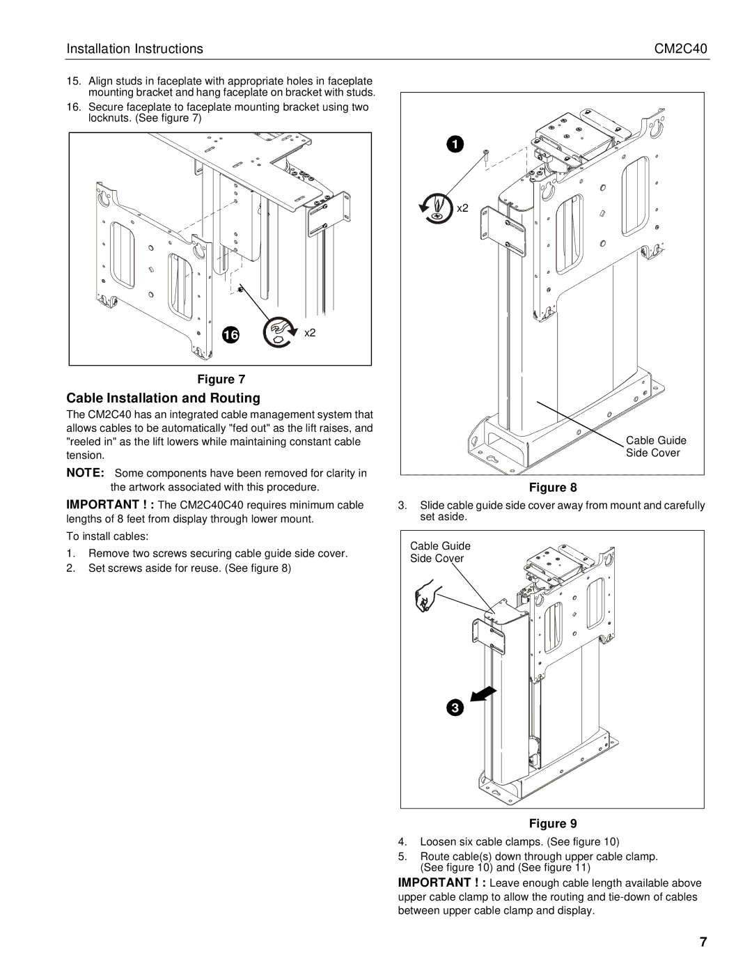
15. Align studs in faceplate with appropriate holes in faceplate |
| |
mounting bracket and hang faceplate on bracket with studs. |
| |
16. Secure faceplate to faceplate mounting bracket using two |
| |
locknuts. (See figure 7) |
|
|
|
| 1 |
|
| x2 |
16 | x2 |
|
Figure 7 |
|
|
Cable Installation and Routing |
|
|
The CM2C40 has an integrated cable management system that |
| |
allows cables to be automatically "fed out" as the lift raises, and | Cable Guide | |
"reeled in" as the lift lowers while maintaining constant cable | ||
tension. |
| Side Cover |
NOTE: Some components have been removed for clarity in |
| |
the artwork associated with this procedure.
IMPORTANT ! : The CM2C40C40 requires minimum cable lengths of 8 feet from display through lower mount.
Figure 8
3.Slide cable guide side cover away from mount and carefully set aside.
To install cables:
1.Remove two screws securing cable guide side cover.
2.Set screws aside for reuse. (See figure 8)
Cable Guide |
Side Cover |
3 |
Figure 9
4.Loosen six cable clamps. (See figure 10)
5.Route cable(s) down through upper cable clamp. (See figure 10) and (See figure 11)
IMPORTANT ! : Leave enough cable length available above upper cable clamp to allow the routing and
7