FSD-4100 specifications
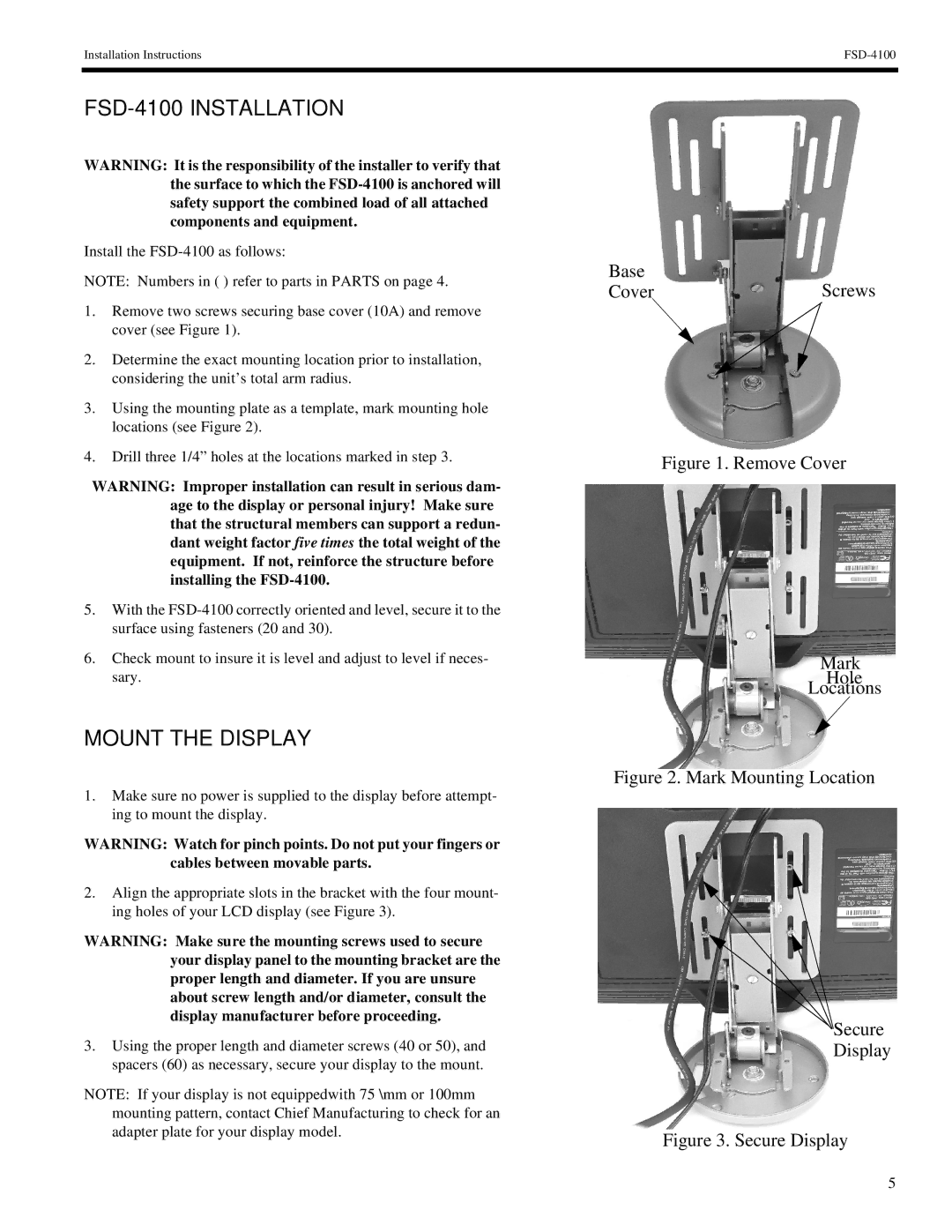
The Chief Manufacturing FSD-4100 is a state-of-the-art flat screen display wall mount designed for commercial applications. This advanced mounting solution exemplifies the perfect blend of functionality, design, and durability, making it an ideal choice for various environments such as conference rooms, classrooms, and retail spaces.One of the standout features of the FSD-4100 is its robust construction. Built from high-quality materials, this mount is capable of supporting large flat panel displays with sizes ranging from 32 to 65 inches. The weight capacity is impressive, accommodating screens up to 175 pounds, which ensures that even the heaviest displays are securely held in place.
The FSD-4100 offers a remarkable level of versatility. Its adjustable design allows for multiple mounting configurations, including portrait and landscape orientations. This flexibility is further enhanced by its easy-to-install features, which include the innovative Quick Release system that allows for fast and simple attachment or removal of the display. With integrated cable management, users can maintain a clean and professional look by concealing cables and reducing clutter.
Another significant characteristic of the FSD-4100 is its tilt and swivel capabilities. This feature enables users to adjust the display’s angle effortlessly, providing optimal viewing experiences from various positions within a room. This is especially useful in collaborative settings where screen visibility from multiple angles is crucial.
In addition to its practical features, the FSD-4100 incorporates Chief’s exclusive Micro-Friction Technology. This cutting-edge technology allows for smooth and precise adjustments without any cumbersome mechanical components. Users can easily modify the screen’s position with minimal effort, ensuring it remains user-friendly even in high-traffic environments.
When it comes to technology, the FSD-4100 is designed with safety in mind. Its heavy-duty design adheres to strict safety standards, ensuring secure installations without sacrificing ease of use. The mount's mounting system includes a comprehensive set of installation hardware, making it compatible with a wide array of wall types.
In summary, the Chief Manufacturing FSD-4100 is an exceptional flat screen display wall mount that stands out due to its durability, versatility, and innovative features. Whether for professional or educational use, it provides an elegant and functional solution for mounting larger displays, enhancing any space with its modern styling and user-friendly design. As technology continues to evolve, the FSD-4100 demonstrates Chief’s commitment to delivering high-quality, reliable products tailored to meet a range of needs in today’s fast-paced environments.

