LVS1U / LVSXU specifications
The Chief Manufacturing LVS1U and LVSXU are state-of-the-art mounting solutions designed for the seamless integration of large displays in various environments, from corporate offices to educational settings and retail spaces. These models are particularly tailored for flat panel displays, providing enhanced functionality, flexibility, and reliability that meet the needs of modern technology.One of the standout features of the LVS1U and LVSXU is their ability to support a wide range of display sizes, typically accommodating screens from 32 inches up to 75 inches. This versatility makes them suitable for a variety of applications, including video conferencing, digital signage, and collaborative workspaces. The mounting solutions are engineered to provide a secure hold, ensuring that the display remains stable even in high-traffic areas.
These models incorporate advanced technologies that enhance the user experience. For example, the LVS1U features a convenient tilting mechanism that allows for easy adjustments to the display angle. This feature is particularly beneficial in environments where glare from overhead lighting can affect visibility. The LVSXU variant takes it a step further by offering additional pivot capabilities, which provide even more flexibility in positioning the screen for optimal viewing.
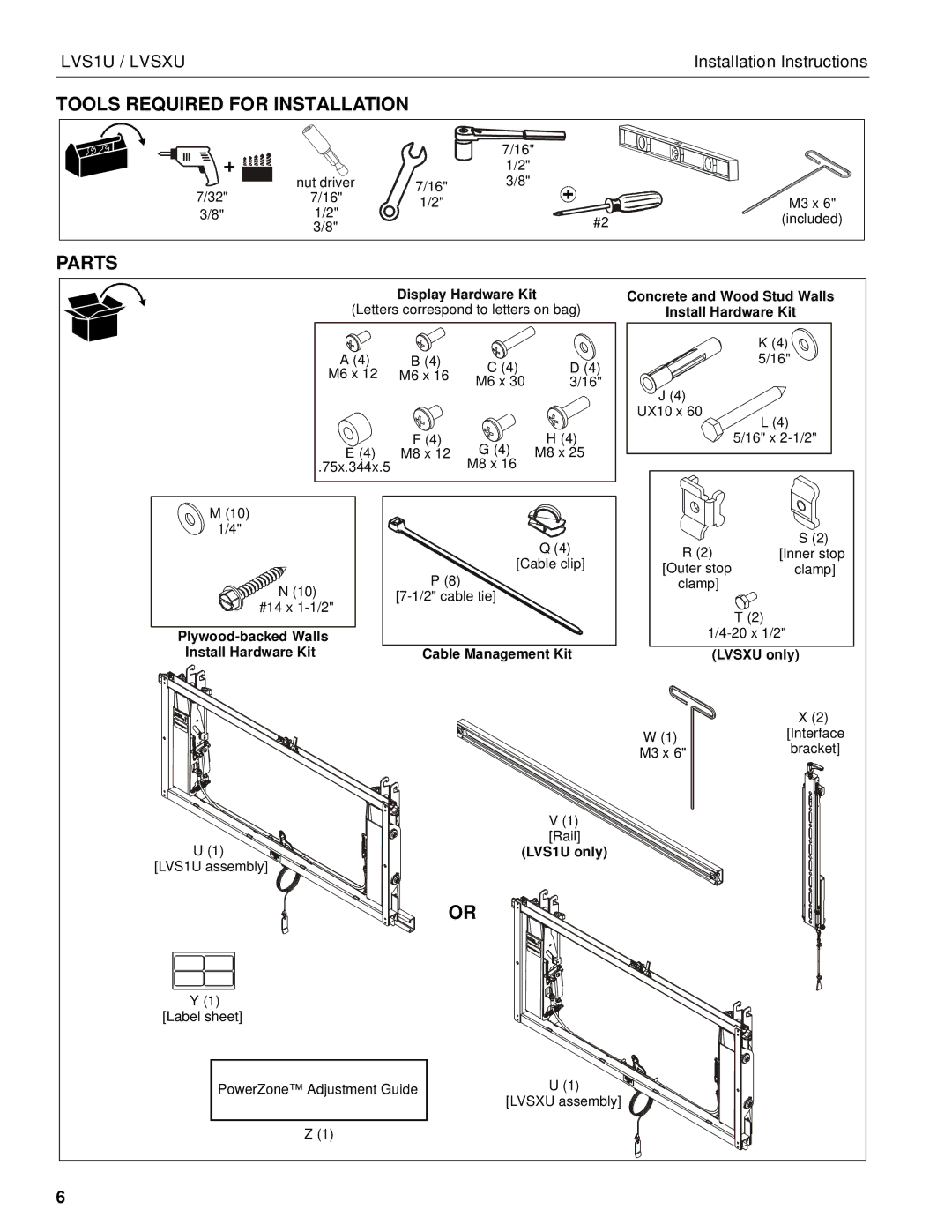
Durability and ease of installation are key characteristics of the LVS1U and LVSXU. Made from high-quality materials, these mountings are designed to withstand the rigors of everyday use. The installation process is straightforward, thanks to integrated cable management systems and adjustable mounting brackets that simplify setup while maintaining a clean appearance. These mountings can be either wall-mounted or placed on a mobile cart, offering further versatility based on the specific layout and spatial requirements of the environment.
Another significant aspect is their compatibility with various VESA patterns, making the LVS1U and LVSXU suitable for a broad spectrum of display models. This adaptability ensures that users can easily upgrade their displays without the need for additional mounting hardware.
In summary, the Chief Manufacturing LVS1U and LVSXU are exceptional solutions for mounting large displays, combining innovative features, advanced technologies, and robust design. Their flexibility, durability, and ease of use make them ideal for modern commercial and educational settings, leading to improved engagement and enhanced viewing experiences.