Install SFP Modules and Connect to the Module Ports
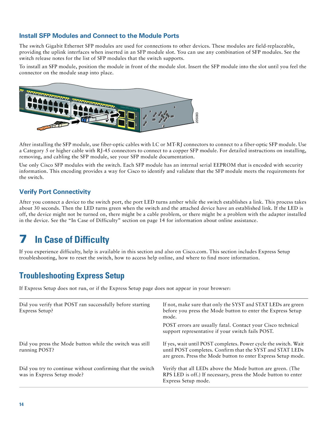
The switch Gigabit Ethernet SFP modules are used for connections to other devices. These modules are
To install an SFP module, position the module in front of the module slot. Insert the SFP module into the slot until you feel the connector on the module snap into place.
Catalyst 2975G
Series
205083
After installing the SFP module, use
Use only Cisco SFP modules with the switch. Each SFP module has an internal serial EEPROM that is encoded with security information. This encoding provides a way for Cisco to identify and validate that the SFP module meets the requirements for the switch.
Verify Port Connectivity
After you connect a device to the switch port, the port LED turns amber while the switch establishes a link. This process takes about 30 seconds. Then the LED turns green when the switch and the attached device have an established link. If the LED is off, the device might not be turned on, there might be a cable problem, or there might be a problem with the adapter installed in the device. See the “In Case of Difficulty” section on page 14 for information about online assistance.
7In Case of Difficulty
If you experience difficulty, help is available in this section and also on Cisco.com. This section includes Express Setup troubleshooting, how to reset the switch, how to access help online, and where to find more information.
Troubleshooting Express Setup
If Express Setup does not run, or if the Express Setup page does not appear in your browser:
Did you verify that POST ran successfully before starting Express Setup?
Did you press the Mode button while the switch was still running POST?
Did you try to continue without confirming that the switch was in Express Setup mode?
If not, make sure that only the SYST and STAT LEDs are green before you press the Mode button to enter the Express Setup mode.
POST errors are usually fatal. Contact your Cisco technical support representative if your switch fails POST.
If yes, wait until POST completes. Power cycle the switch. Wait until POST completes. Confirm that the SYST and STAT LEDs are green. Press the Mode button to enter Express Setup mode.
Verify that all LEDs above the Mode button are green. (The RPS LED is off.) If necessary, press the Mode button to enter Express Setup mode.
14
