Chapter 2 Installation
Installing Your Router
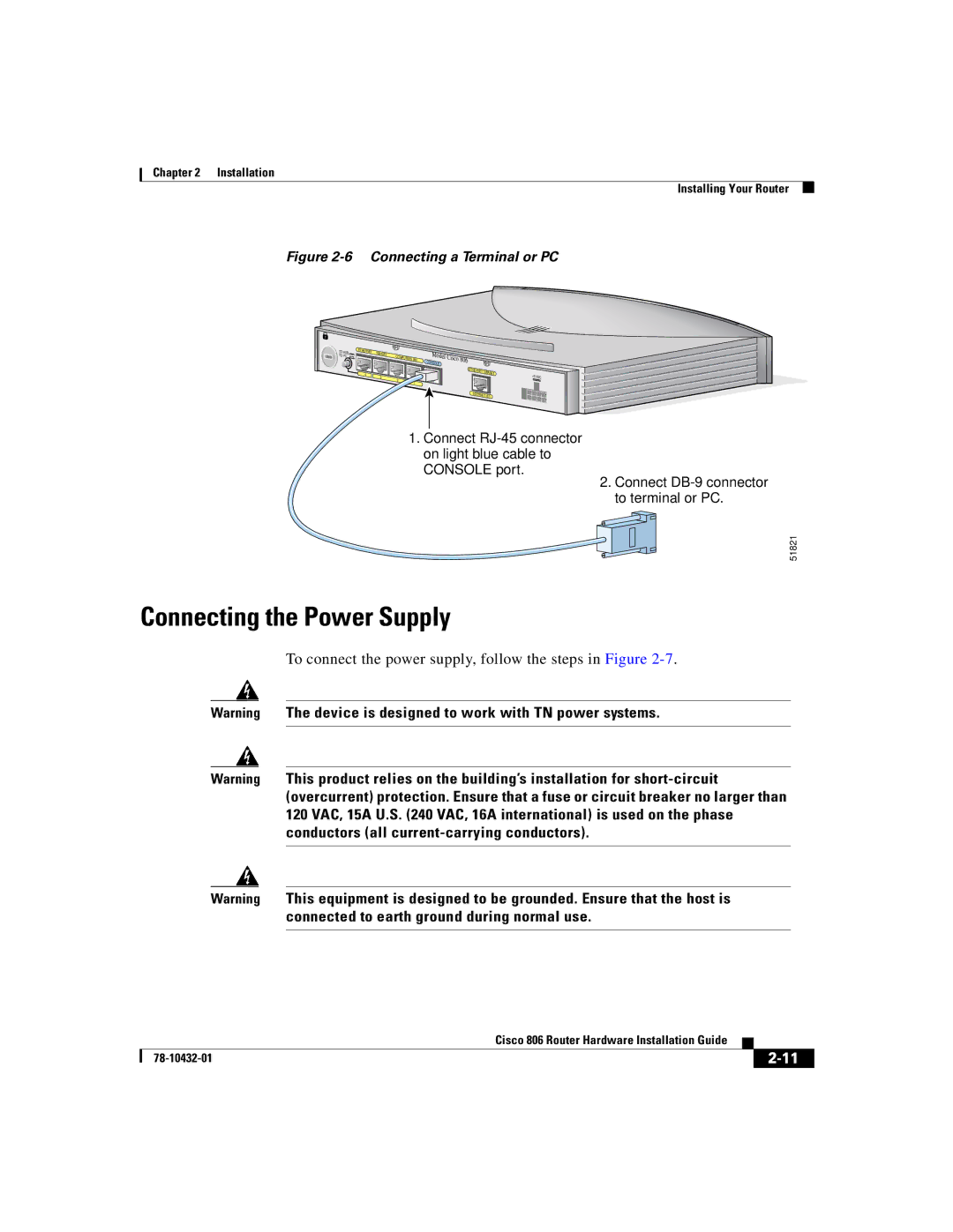
Figure 2-6 Connecting a Terminal or PC
TO HUB | ETHERNET | 10BASET |
|
TO PC |
| COMPUTERS (E0) | |
|
|
| |
| 4 | 3 |
|
|
| 2 | |
|
|
| |
|
|
| 1 |
Model | |
CONSOLE | Cisco 806 |
ETHERNET |
|
10BASET | +5 VDC |
INTERNET (E1) |
|
1.Connect
2. Connect
51821
Connecting the Power Supply
To connect the power supply, follow the steps in Figure 2-7.
Warning The device is designed to work with TN power systems.
Warning This product relies on the building’s installation for
Warning This equipment is designed to be grounded. Ensure that the host is connected to earth ground during normal use.
|
| Cisco 806 Router Hardware Installation Guide |
|
|
|
|
| ||
|
|
| ||
|
|
|