Chapter 3 Troubleshooting
|
|
| Problems After Router Is Running |
|
Table |
| |||
|
|
|
| |
Symptom | Problem | Solutions |
| |
|
|
|
| |
No connection to | A | Perform the following tasks in order: |
| |
Ethernet devices. | problem: | 1. To make sure that you have cabled the device |
| |
|
|
|
| |
(COMPUTER | • | Improperly | correctly, see Figure |
|
LEDs 1 through 4 |
| connected cable. | “Installation.” |
|
are off.) | • | Damaged cable. | 2. Make sure that the connectors at both ends of the |
|
|
| |||
|
|
| cable are securely seated. |
|
|
|
| 3. Make sure the cable is not physically damaged. If it |
|
|
|
| is, order another cable from Cisco Systems, or |
|
|
|
| replace it with a similar cable |
|
|
|
|
| |
| Improper setting of TO | To make sure that the button is set correctly, see |
| |
| HUB/TO PC button on | Table |
| |
| router or hub. |
|
| |
|
|
|
|
|
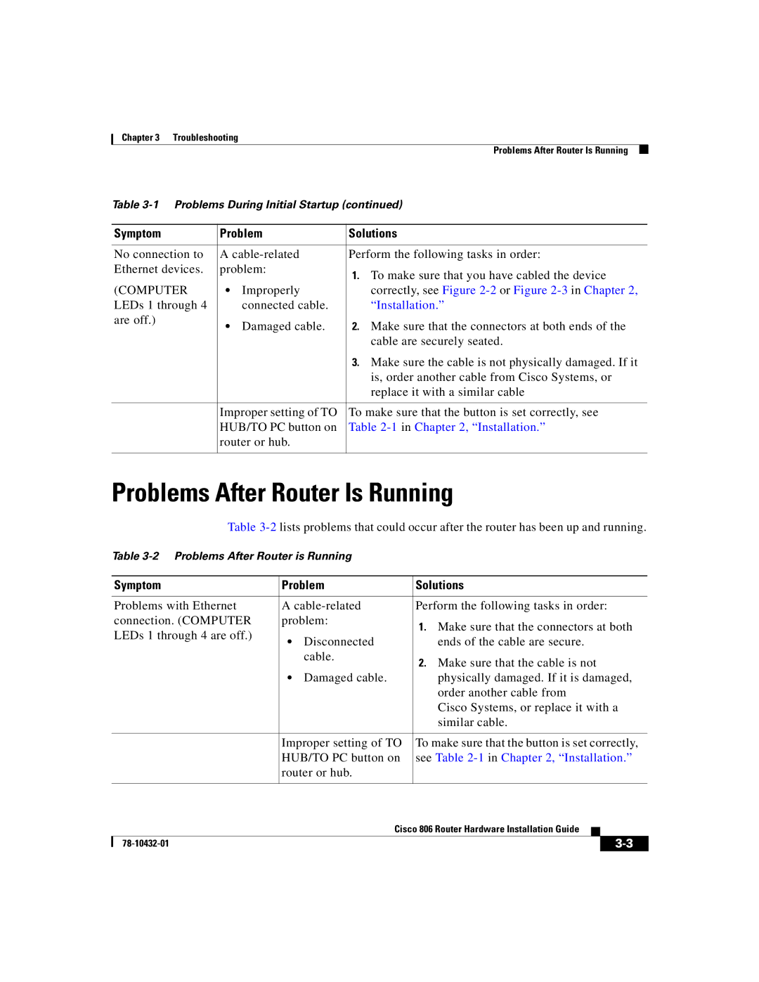
Problems After Router Is Running
Table
Table
| Symptom | Problem | Solutions | |||
|
|
|
| |||
| Problems with Ethernet | A | Perform the following tasks in order: | |||
| connection. (COMPUTER | problem: | 1. Make sure that the connectors at both | |||
| LEDs 1 through 4 are off.) |
|
| |||
| • | Disconnected | ends of the cable are secure. | |||
|
| |||||
|
|
| cable. | 2. Make sure that the cable is not | ||
|
|
|
| |||
|
| • | Damaged cable. | physically damaged. If it is damaged, | ||
|
|
|
| order another cable from | ||
|
|
|
| Cisco Systems, or replace it with a | ||
|
|
|
| similar cable. | ||
|
|
|
| |||
|
| Improper setting of TO | To make sure that the button is set correctly, | |||
|
| HUB/TO PC button on | see Table | |||
|
| router or hub. |
|
|
| |
|
|
|
|
|
|
|
|
|
| Cisco 806 Router Hardware Installation Guide |
|
| |
|
|
|
| |||
|
|
|
|
| ||
|
|
|
|
| ||