Chapter 3 Troubleshooting
Problems After Router Is Running
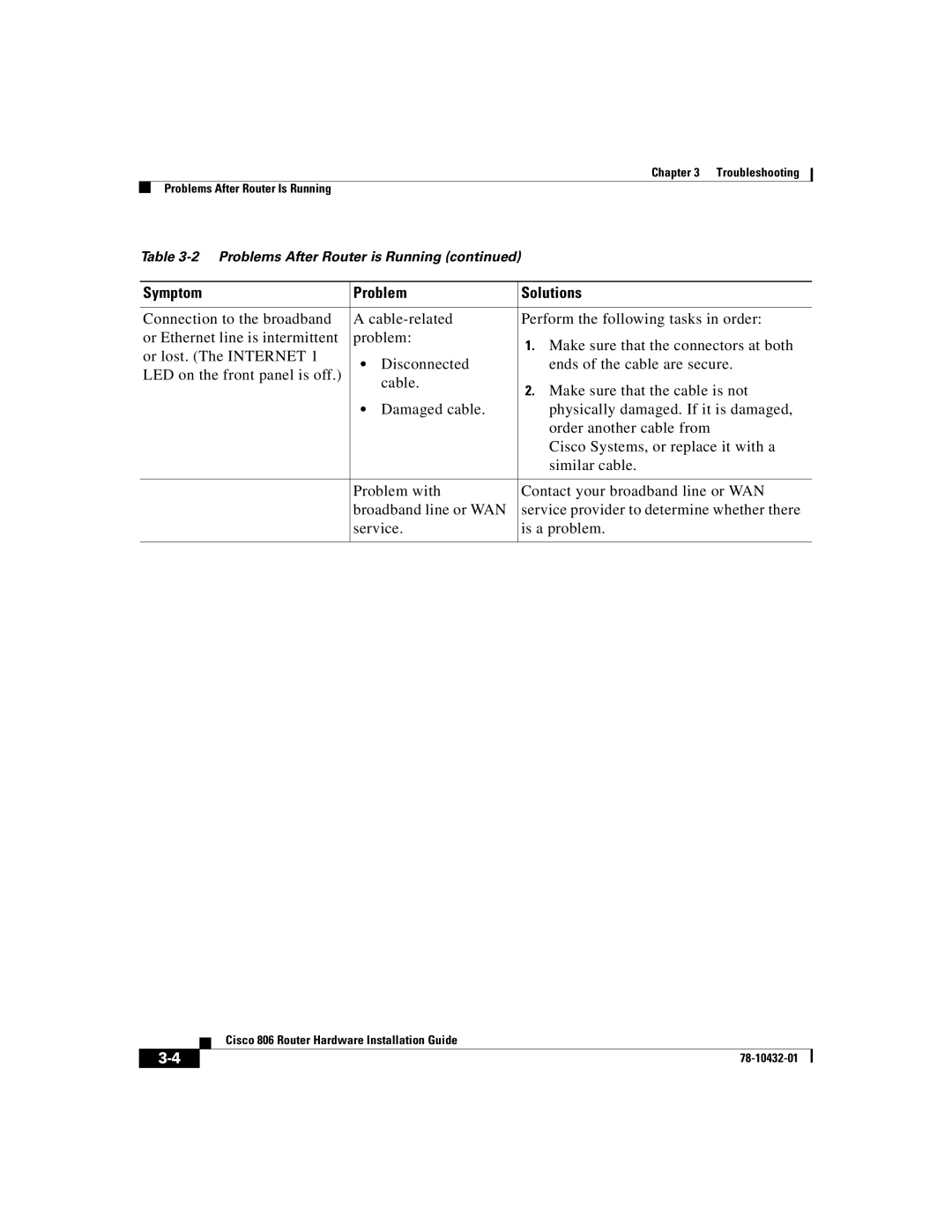
Table
Symptom | Problem | Solutions | ||
|
|
| ||
Connection to the broadband | A | Perform the following tasks in order: | ||
or Ethernet line is intermittent | problem: | 1. Make sure that the connectors at both | ||
or lost. (The INTERNET 1 |
|
| ||
• | Disconnected | ends of the cable are secure. | ||
LED on the front panel is off.) | ||||
| cable. | 2. Make sure that the cable is not | ||
|
| |||
|
|
| ||
| • | Damaged cable. | physically damaged. If it is damaged, | |
|
|
| order another cable from | |
|
|
| Cisco Systems, or replace it with a | |
|
|
| similar cable. | |
|
|
| ||
| Problem with | Contact your broadband line or WAN | ||
| broadband line or WAN | service provider to determine whether there | ||
| service. | is a problem. | ||
|
|
|
| |
| Cisco 806 Router Hardware Installation Guide |