Customer Order Number DOC-7810432= Text Part Number
Cisco 806 Router Hardware Installation Guide
Corporate Headquarters
Turn the television or radio antenna until the interference stops
Move the equipment farther away from the television or radio
Cisco 806 Router Hardware Installation Guide
Copyright 2001, Cisco Systems, Inc All rights reserved
Page
Contacting TAC by Using the Cisco TAC Website
Preface
Audience
World Wide Web
Installation
Safety
Troubleshooting
Preparing for Installation
System Specifications A-1 Port Connector Pinouts A-2
Cabling Specifications A-4 Ethernet Cable Specifications A-4
Maximum Cable Distances A-5
Contents
viii
Contents
Cisco 806 Router Hardware Installation Guide
78-10432-01
Organization
Preface
Audience
Conventions
¡Atención! Este símbolo de aviso significa peligro. Existe riesgo para su integridad física. Antes de manipular cualquier equipo, considerar los riesgos que entraña la corriente eléctrica y familiarizarse con los procedimientos estándar de prevención de accidentes
Related Documentation
Obtaining Documentation
World Wide Web
http//www-china.cisco.com http//www-europe.cisco.com
Documentation CD-ROM
Ordering Documentation
Documentation Feedback
xiii
Obtaining Technical Assistance
Cisco.com
Contacting TAC by Telephone
Contacting TAC by Using the Cisco TAC Website
Technical Assistance Center
78-10432-01
Cisco 806 Router Hardware Installation Guide
Preface Obtaining Technical Assistance
C H A P T E R
Features
Product Overview
Router Overview
Front Panel
Back Panel
Figure 1-1 Cisco 806 Front Panel
Figure 1-2 Cisco 806 Back Panel
Chapter 1 Product Overview Router Overview
Function
LEDs
Color
Installation
Preparing for Installation
Safety
Preparing for Installation Preventing Router Damage
Warnings
Before installing the router, read the following warnings
Preventing Electrostatic Discharge Damage
Unpacking the Box
Installing Your Router
Preventing Router Damage
Connecting Ethernet Devices
Connecting a Hub
Figure 2-2 Connecting a Hub
Connecting a Server, PC, or Workstation
Figure 2-3 Connecting a Server, PC, or Workstation
Connecting to the Internet
Connecting a Broadband Modem
2-10
Connecting a Terminal or PC to the Console Port
Connecting an Ethernet Switch
Connecting the Power Supply
2-11
Verifying Your Router Installation
2-12
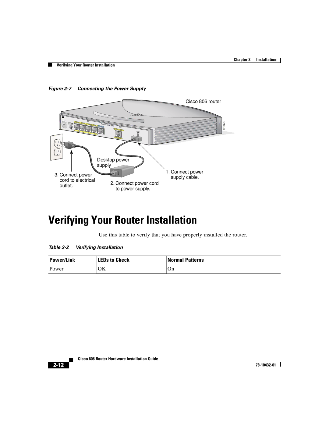
Figure 2-7 Connecting the Power Supply
Desktop power supply
2-13
Mounting Your Router
Mounting on Table
Mounting on Wall
2-14
2-15
The power supply must rest on a horizontal surface such as the floor or a table. If the power supply is not supported, it might place strain on the power supply cable and cause it to disconnect from the connector on the router back panel
2-16
3. Place power supply
Chapter 2 Installation Mounting Your Router
Cisco 806 Router Hardware Installation Guide
http//10.10.10.1
Where to Go from Here
2-17
2-18
Chapter 2 Installation Where to Go from Here
Cisco 806 Router Hardware Installation Guide
78-10432-01
Troubleshooting
Problems During Initial Startup Problems After Router Is Running
Before You Call Your Cisco Reseller
C H A P T E R
Problems During Initial Startup
“Installation.”
correctly, see Figure 2-4 or Figure 2-5 in Chapter
Symptom
Problems After Router Is Running
Table 2-1 in Chapter 2, “Installation.”
see Table 2-1 in Chapter 2, “Installation.”
correctly, see Figure 2-2 or Figure 2-3 in Chapter
Symptom
Problem
Solutions
Table 3-2 Problems After Router is Running continued
A P P E N D I X A
Specifications and Cables
System Specifications
Port Connector Pinouts
Ethernet-See Table A-2, Table A-5, and Table A-6
Table A-2 Cisco 806 Router Ethernet Connector Pinouts RJ-45
Table A-3 Console Connector Pinouts RJ-45
Cabling Specifications
Ethernet Cable Specifications
Maximum Cable Distances
Table A-5 Ethernet Cable Specifications
Appendix A Specifications and Cables Cabling Specifications
Cisco 806 Router Hardware Installation Guide
78-10432-01
Appendix A Specifications and Cables Cabling Specifications
Cisco 806 Router Hardware Installation Guide
GL-1
Numerics
G L O S S A R Y
GL-2
GL-3
GL-4
Numerics
I N D E
IN-1
IN-2
IN-3
IN-4
Cisco 806 Router Hardware Installation Guide
Index
78-10432-01
To check scale 1 inch 2.54 cm
Router Wall-Mount Template
758 inches 19.35 cm