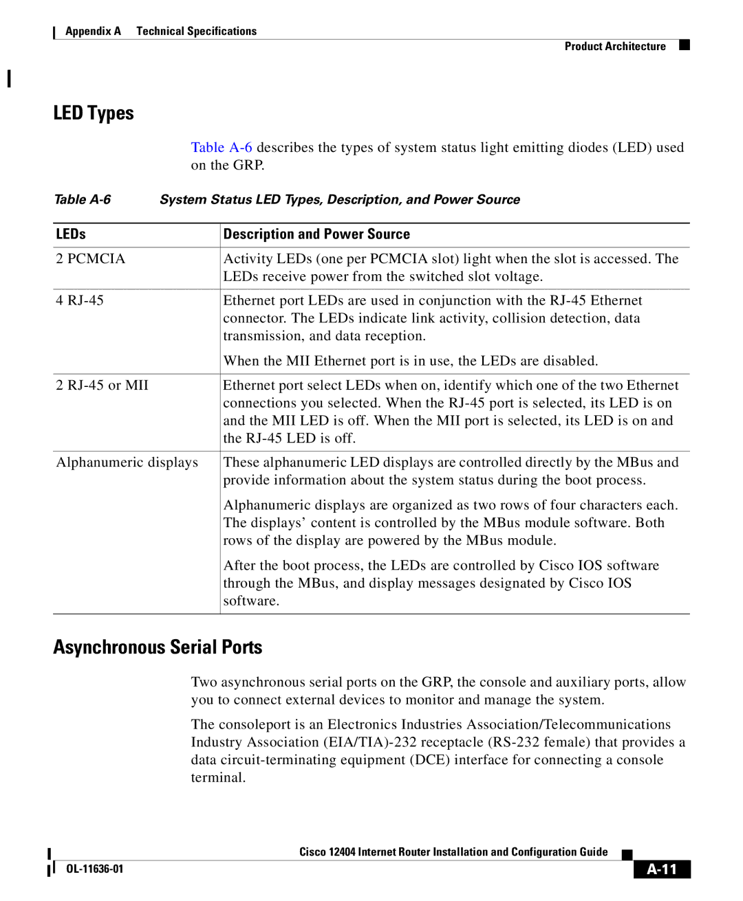
Cisco 12404 specifications
The Cisco 12404 is a robust router designed for service providers and large enterprises, aiming to deliver high performance, scalability, and flexibility in networking. As part of the Cisco 12000 Series, the 12404 is built to address the demands of high-bandwidth applications and a growing number of users in modern networks.One of the standout features of the Cisco 12404 is its versatility. The router supports various modules for enhanced functionality, including high-speed interfaces, advanced processing capabilities, and additional memory. This modular design allows organizations to customize their router according to specific networking needs and expand as requirements evolve.
In terms of performance, the Cisco 12404 is equipped with a high-capacity forwarding engine that ensures rapid data transfer and low latency. This capability is crucial for businesses that rely on real-time communication, such as VoIP and video conferencing. The router supports a variety of protocols, including IP, MPLS, and Ethernet, making it adaptable to diverse operational environments.
Scalability is another significant characteristic of the Cisco 12404. It can handle thousands of routes and high volumes of traffic, making it suitable for ISPs managing large subscriber bases. With its support for 10 Gigabit and 100 Gigabit Ethernet interfaces, the router can accommodate increasing data loads without compromising performance.
Advanced features like Quality of Service (QoS) enable network administrators to prioritize traffic based on the type or importance of data. This ensures that critical applications receive the bandwidth they need while less essential services are deprioritized, thus optimizing overall network efficiency.
The Cisco 12404 also integrates advanced security measures to protect sensitive data as it flows through the network. With features like Access Control Lists (ACLs), Virtual Private Network (VPN) support, and encryption capabilities, organizations can safeguard their information against potential threats.
In conclusion, the Cisco 12404 presents a compelling solution for organizations seeking a high-performance router with scalability and versatility. By combining advanced routing technologies, modular design, and robust security features, it stands out as a reliable choice for enterprises and service providers looking to optimize their core networking infrastructure.

