Appendix C Cable and Port Specifications
Supported Power Cords and Plugs
Table
Table | ||
|
|
|
Pin | Signal | |
|
|
|
1 | TD+ | |
|
|
|
2 | TD- | |
|
|
|
3 | RD+ | |
|
|
|
6 | RD– | |
|
|
|
4 | Not used | |
|
|
|
5 | Not used | |
|
|
|
7 | Not used | |
|
|
|
8 | Not used | |
|
|
|
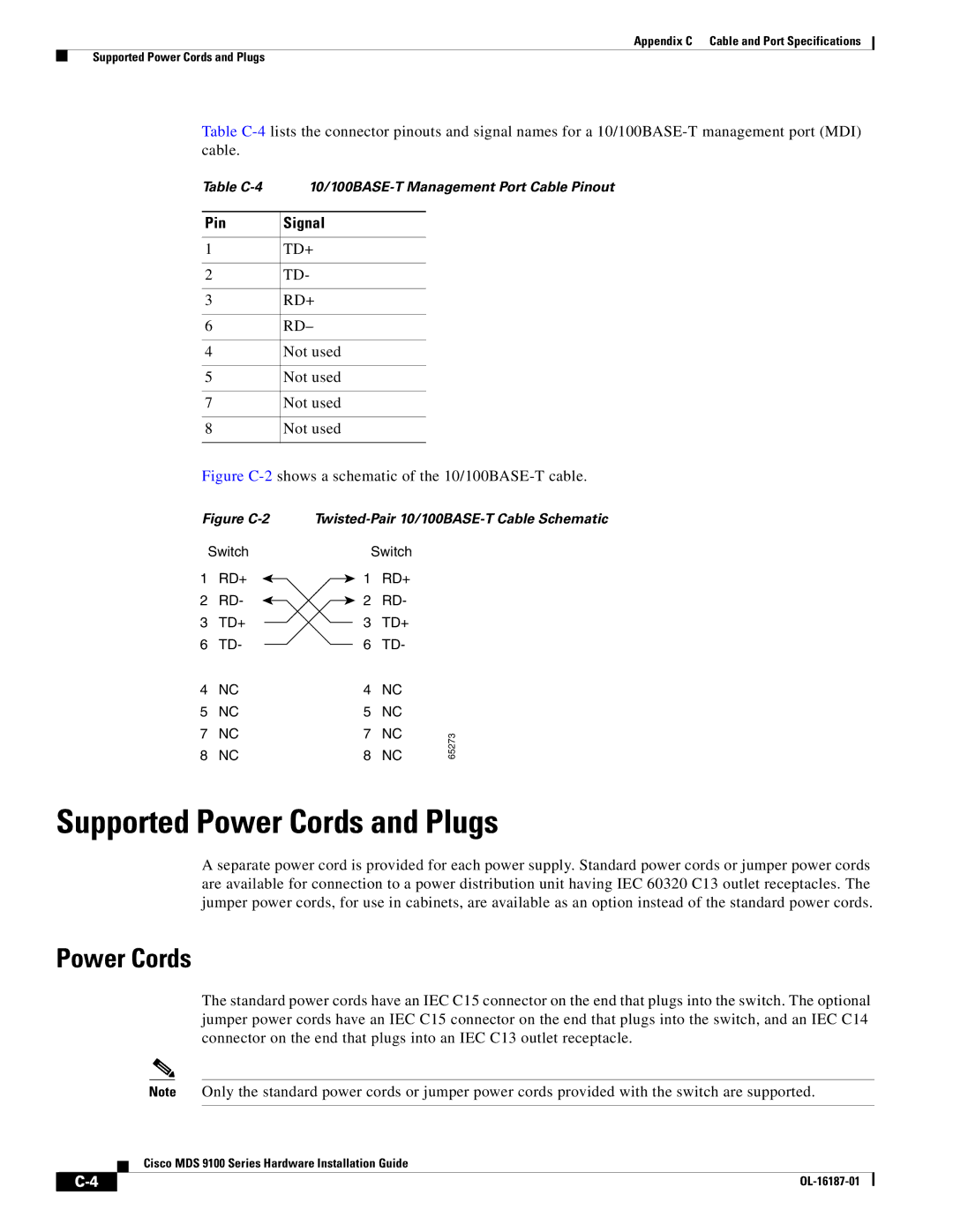
Figure C-2 shows a schematic of the 10/100BASE-T cable.
Figure C-2
Switch
1 RD+
2 RD-
3TD+
6TD-
4NC
5NC
7NC
8NC
| Switch |
| |
1 | RD+ |
| |
2 | RD- |
| |
3 | TD+ |
| |
6 | TD- |
| |
4 | NC |
| |
5 | NC |
| |
7 | NC | 65273 | |
8 | NC | ||
|
Supported Power Cords and Plugs
A separate power cord is provided for each power supply. Standard power cords or jumper power cords are available for connection to a power distribution unit having IEC 60320 C13 outlet receptacles. The jumper power cords, for use in cabinets, are available as an option instead of the standard power cords.
Power Cords
The standard power cords have an IEC C15 connector on the end that plugs into the switch. The optional jumper power cords have an IEC C15 connector on the end that plugs into the switch, and an IEC C14 connector on the end that plugs into an IEC C13 outlet receptacle.
Note Only the standard power cords or jumper power cords provided with the switch are supported.
Cisco MDS 9100 Series Hardware Installation Guide
|
| ||
|
|