Appendix B Technical Specifications
Power Specifications
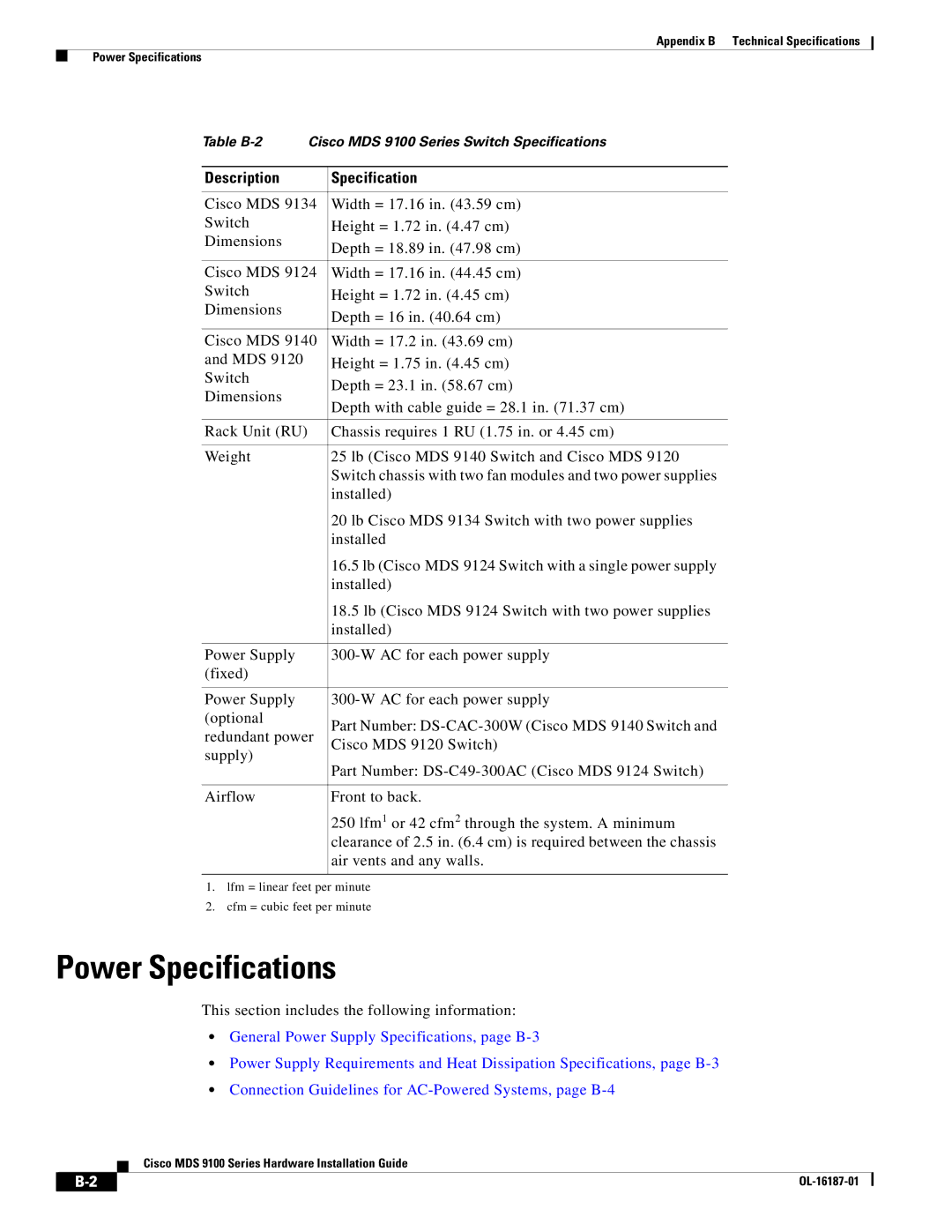
Table
Description | Specification | |
|
| |
Cisco MDS 9134 | Width = 17.16 in. (43.59 cm) | |
Switch | Height = 1.72 in. (4.47 cm) | |
Dimensions | Depth = 18.89 in. (47.98 cm) | |
| ||
|
| |
Cisco MDS 9124 | Width = 17.16 in. (44.45 cm) | |
Switch | Height = 1.72 in. (4.45 cm) | |
Dimensions | Depth = 16 in. (40.64 cm) | |
| ||
|
| |
Cisco MDS 9140 | Width = 17.2 in. (43.69 cm) | |
and MDS 9120 | Height = 1.75 in. (4.45 cm) | |
Switch | Depth = 23.1 in. (58.67 cm) | |
Dimensions | ||
Depth with cable guide = 28.1 in. (71.37 cm) | ||
| ||
|
| |
Rack Unit (RU) | Chassis requires 1 RU (1.75 in. or 4.45 cm) | |
|
| |
Weight | 25 lb (Cisco MDS 9140 Switch and Cisco MDS 9120 | |
| Switch chassis with two fan modules and two power supplies | |
| installed) | |
| 20 lb Cisco MDS 9134 Switch with two power supplies | |
| installed | |
| 16.5 lb (Cisco MDS 9124 Switch with a single power supply | |
| installed) | |
| 18.5 lb (Cisco MDS 9124 Switch with two power supplies | |
| installed) | |
|
| |
Power Supply | ||
(fixed) |
| |
|
| |
Power Supply | ||
(optional | Part Number: | |
redundant power | ||
Cisco MDS 9120 Switch) | ||
supply) | ||
Part Number: | ||
| ||
|
| |
Airflow | Front to back. | |
| 250 lfm1 or 42 cfm2 through the system. A minimum | |
| clearance of 2.5 in. (6.4 cm) is required between the chassis | |
| air vents and any walls. | |
|
|
1.lfm = linear feet per minute
2.cfm = cubic feet per minute
Power Specifications
This section includes the following information:
•General Power Supply Specifications, page
•Power Supply Requirements and Heat Dissipation Specifications, page
•Connection Guidelines for
Cisco MDS 9100 Series Hardware Installation Guide
|
| ||
|
|