Chapter 2 Installing the Cisco MDS 9100 Series
Installing the Switch in a Cabinet with Insufficient Front Clearance
Step 2 Insert the switch into the rack:
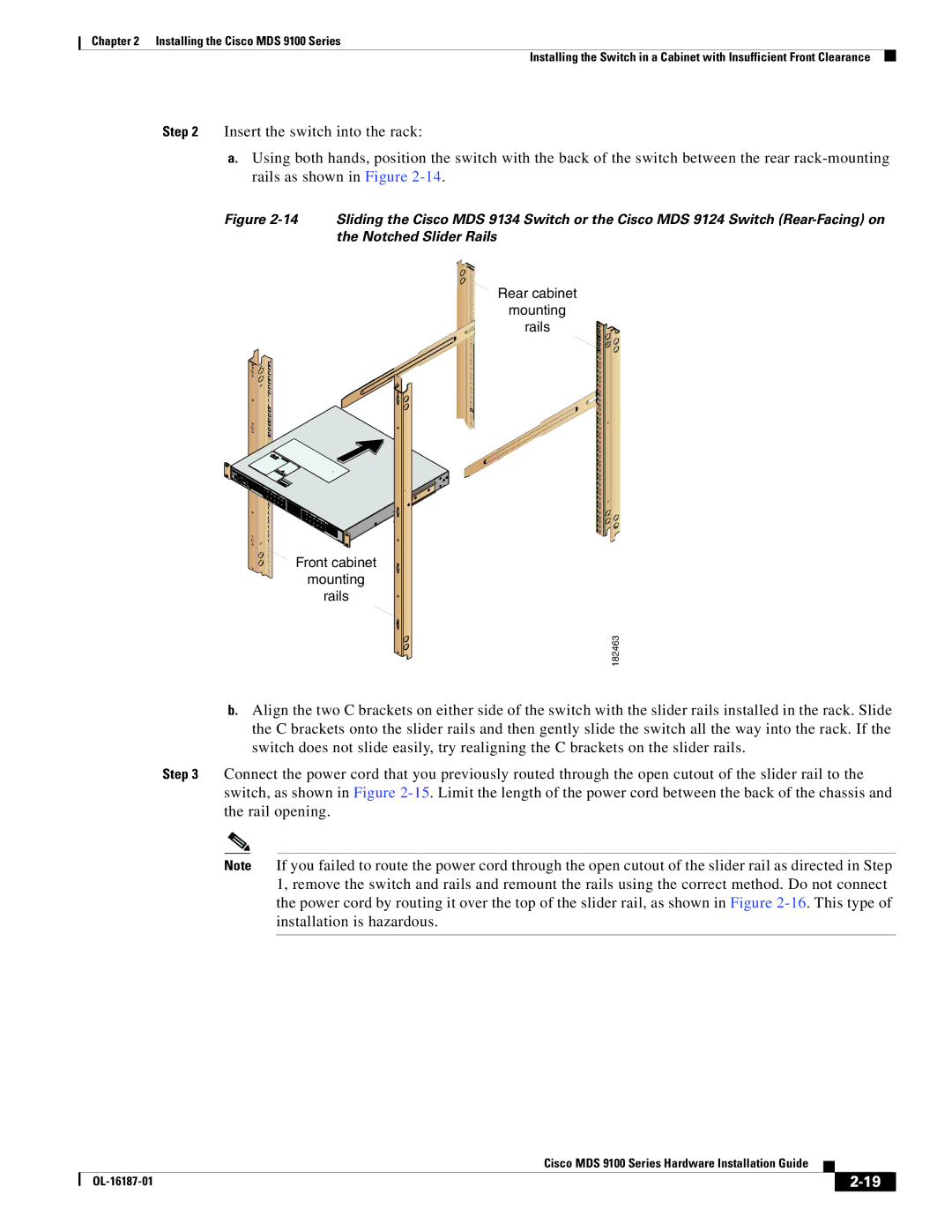
a.Using both hands, position the switch with the back of the switch between the rear
Figure 2-14 Sliding the Cisco MDS 9134 Switch or the Cisco MDS 9124 Switch (Rear-Facing) on the Notched Slider Rails
Rear cabinet
mounting
rails
Front cabinet
mounting
rails
182463
b.Align the two C brackets on either side of the switch with the slider rails installed in the rack. Slide the C brackets onto the slider rails and then gently slide the switch all the way into the rack. If the switch does not slide easily, try realigning the C brackets on the slider rails.
Step 3 Connect the power cord that you previously routed through the open cutout of the slider rail to the switch, as shown in Figure
Note If you failed to route the power cord through the open cutout of the slider rail as directed in Step 1, remove the switch and rails and remount the rails using the correct method. Do not connect the power cord by routing it over the top of the slider rail, as shown in Figure
|
| Cisco MDS 9100 Series Hardware Installation Guide |
|
| |
|
|
| |||
|
|
|
| ||
|
|
|
| ||