Chapter 2 Installing the Cisco MDS 9100 Series
Installing the Switch in a Cabinet with Insufficient Front Clearance
Step 2 Insert the switch into the rack:
a.By using both hands, position the switch with the back of the switch between the rear
Note Figure
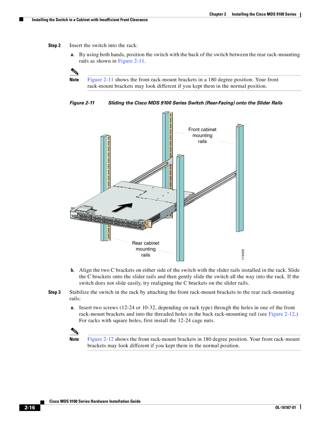
Figure 2-11 Sliding the Cisco MDS 9100 Series Switch (Rear-Facing) onto the Slider Rails
Front cabinet
mounting
rails
Rear cabinet
mounting
rails
113429
b.Align the two C brackets on either side of the switch with the slider rails installed in the rack. Slide the C brackets onto the slider rails and then gently slide the switch all the way into the rack. If the switch does not slide easily, try realigning the C brackets on the slider rails.
Step 3 Stabilize the switch in the rack by attaching the front
a.Insert two screws
Note Figure
| Cisco MDS 9100 Series Hardware Installation Guide |