Maintaining Safe Installation Distances
Maintaining Safe Installation Distances
Except at the edge connector that plugs into the host chassis expansion slot, clearance and creepage distances of x millimeters (mm) and y mm as listed in Table 1 must be maintained between the cards and other parts of the host, including any other expansion cards fitted.
Table 1 | Creepage and Clearance Distances Based on Voltage |
| ||
|
|
| ||
Voltage Used or Generated by Other Parts of the | Creepage | Clearance | ||
Host or Expansion Card (Vrms1 or VDC2) | (y mm)3 | (x mm) | ||
Up to 50 |
| 2.4 | (3.8) | 2.0 |
|
|
|
| |
Up to 125 |
| 3.0 (4.8) | 2.6 | |
|
|
|
| |
Up to 250 |
| 5.0 (8.0) | 4.0 | |
|
|
|
|
|
Up to 300 |
| 6.4 | (10.0) | 4.0 |
|
|
|
|
|
1.Vrms = root mean square voltage.
2.VDC = volts direct current
3.The creepage distances not in parentheses apply when the equipment is installed in a normal office environment. The larger dimensions, in parentheses, must be applied when the equipment is installed in an environment in which dust and other types of pollution could conduct electricity because of the effects of dampness and condensation. This applies to locations subject to high humidity.
Clearance distances are defined as the minimum distance measured in air between two points (that is, line of sight).
Creepage distances are defined as the minimum distance measured across the surface of an insulator between two points (that is, following the contour of the insulator).
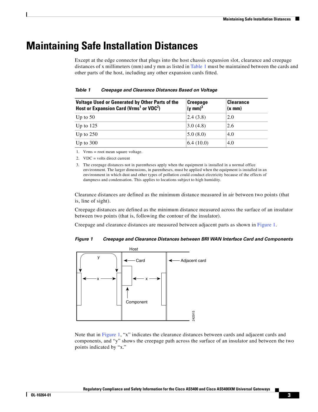
Creepage and clearance distances are measured between adjacent parts as shown in Figure 1.
Figure 1 Creepage and Clearance Distances between BRI WAN Interface Card and Components
Host
y
Card |
| Adjacent card |
|
x |
|
|
|
|
| x |
|
|
|
| |||
|
|
|
|
|
|
|
Component
242915
Note that in Figure 1, “x” indicates the clearance distances between cards and adjacent cards and components, and “y” shows the creepage path across the surface of an insulator and between the two points indicated by “x.”
Regulatory Compliance and Safety Information for the Cisco AS5400 and Cisco AS5400XM Universal Gateways
| 3 |
| |
|
|