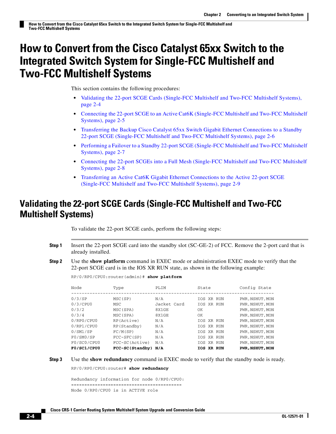
CRS-1 specifications
Cisco Systems' Carrier Routing System (CRS-1) is a cutting-edge, high-capacity router designed to meet the demands of service providers and large enterprises. Introduced in the early 2000s, the CRS-1 represents a significant leap forward in routing technology, offering unparalleled performance, scalability, and reliability.One of the primary features of the CRS-1 is its exceptional scalability. The system is built on a modular architecture that allows for easy upgrades and expansions. This enables service providers to start with a configuration that suits their immediate needs while having the flexibility to expand as traffic demands grow. The CRS-1 supports a wide range of line cards, enabling data, voice, and video to be managed on a single platform, which simplifies network management and reduces operating costs.
The CRS-1 leverages advanced technologies that enable it to deliver impressive performance. With the ability to handle up to 92 terabits per second of throughput, the router is capable of supporting a vast number of connections, making it well-suited for large-scale service providers and data centers. This level of performance is powered by Cisco’s proprietary silicon technology, which optimizes the packet forwarding process and enhances overall efficiency.
Another key characteristic of the CRS-1 is its strong focus on reliability and redundancy. The system is designed with high availability in mind, ensuring that it can continue to operate seamlessly even in the event of hardware failures. Redundant components, such as power supplies and route processors, allow the CRS-1 to maintain its performance and uptime, a critical requirement for mission-critical network operations.
Additionally, the CRS-1 supports a wide variety of protocols and technologies, including Internet Protocol (IP), Multiprotocol Label Switching (MPLS), and various service provider features. This versatility makes it a compelling choice for organizations looking to implement advanced networking capabilities, such as Quality of Service (QoS) and traffic engineering.
In summary, the Cisco Systems CRS-1 stands out as a formidable solution for modern routing needs. Its modular design, exceptional scalability, robust performance, reliability, and support for multiple protocols and services make it an ideal choice for service providers and enterprises seeking to future-proof their networks. As the demand for bandwidth continues to surge, the CRS-1 remains a pivotal component in the evolution of networking infrastructure.

