|
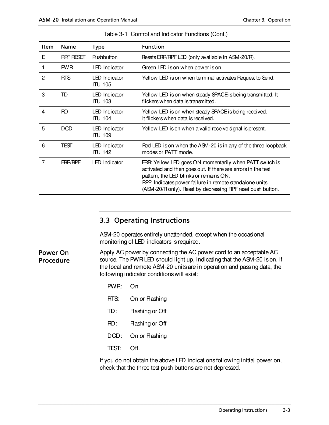
| Table | Control and Indicator Functions (Cont.) |
|
|
|
|
Item | Name | Type | Function |
|
|
|
|
E | RPF RESET | Pushbutton | Resets ERR/RPF LED (only available in |
|
|
|
|
1 | PWR | LED Indicator | Green LED is on when power is on. |
|
|
|
|
2 | RTS | LED Indicator | Yellow LED is on when terminal activates Request to Send. |
|
| ITU 105 |
|
|
|
|
|
3 | TD | LED Indicator | Yellow LED is on when steady SPACE is being transmitted. It |
|
| ITU 103 | flickers when data is transmitted. |
|
|
|
|
4 | RD | LED Indicator | Yellow LED is on when steady SPACE is being received. |
|
| ITU 104 | It flickers when data is received. |
|
|
|
|
5 | DCD | LED Indicator | Yellow LED is on when a valid receive signal is present. |
|
| ITU 109 |
|
|
|
|
|
6 | TEST | LED Indicator | Red LED is on when the |
|
| ITU 142 | modes or PATT mode. |
|
|
|
|
7 | ERR/RPF | LED Indicator | ERR: Yellow LED goes ON momentarily when PATT switch is |
|
|
| activated and then goes out. If there are errors in the test |
|
|
| pattern, the LED blinks or remains ON. |
RPF: Indicates power failure in remote standalone units
Power On Procedure
3.3 Operating Instructions
Apply AC power by connecting the AC power cord to an acceptable AC source. The PWR LED should light up, indicating that the
∙PWR: On
∙ | RTS: | On or Flashing |
∙ | TD: | Flashing or Off |
∙ | RD: | Flashing or Off |
∙DCD: On or Flashing
∙TEST: Off.
If you do not obtain the above LED indications following initial power on, check that the three test push buttons are not depressed.
Operating Instructions |