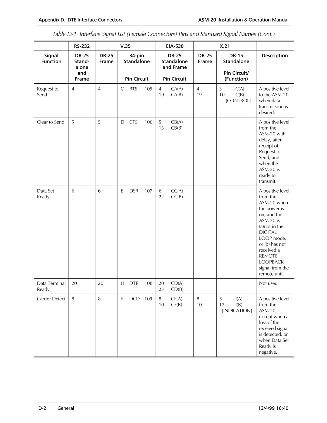
Appendix D. DTE Interface ConnectorsASM-20Installation & Operation Manual
Table
|
| V.35 |
|
|
| X.21 |
| ||||
|
|
|
|
|
|
|
|
|
|
|
|
Signal |
|
|
|
| Description | ||||||
Function | Stand- | Frame | Standalone | Standalone | Frame | Standalone |
| ||||
| alone |
|
|
|
| and Frame |
|
|
|
| |
| and |
|
|
|
|
|
|
| Pin Circuit/ |
| |
| Frame |
|
| Pin Circuit | Pin Circuit |
|
| (Function) |
| ||
|
|
|
|
|
|
|
|
|
|
|
|
Request to | 4 | 4 | C | RTS | 105 | 4 | CA(A) | 4 | 3 | C(A) | A positive level |
Send |
|
|
|
|
| 19 | CA(B) | 19 | 10 | C(B) | to the |
|
|
|
|
|
|
|
|
|
| [CONTROL] | when data |
|
|
|
|
|
|
|
|
|
|
| transmission is |
|
|
|
|
|
|
|
|
|
|
| desired. |
|
|
|
|
|
|
|
|
|
|
|
|
Clear to Send | 5 | 5 | D | CTS | 106 | 5 | CB(A) |
|
|
| A positive level |
|
|
|
|
|
| 13 | CB(B) |
|
|
| from the |
|
|
|
|
|
|
|
|
|
|
| |
|
|
|
|
|
|
|
|
|
|
| delay, after |
|
|
|
|
|
|
|
|
|
|
| receipt of |
|
|
|
|
|
|
|
|
|
|
| Request to |
|
|
|
|
|
|
|
|
|
|
| Send, and |
|
|
|
|
|
|
|
|
|
|
| when the |
|
|
|
|
|
|
|
|
|
|
| |
|
|
|
|
|
|
|
|
|
|
| ready to |
|
|
|
|
|
|
|
|
|
|
| transmit. |
|
|
|
|
|
|
|
|
|
|
|
|
Data Set | 6 | 6 | E | DSR | 107 | 6 | CC(A) |
|
|
| A positive level |
Ready |
|
|
|
|
| 22 | CC(B) |
|
|
| from the |
|
|
|
|
|
|
|
|
|
|
| |
|
|
|
|
|
|
|
|
|
|
| the power is |
|
|
|
|
|
|
|
|
|
|
| on, and the |
|
|
|
|
|
|
|
|
|
|
| |
|
|
|
|
|
|
|
|
|
|
| (a)not in the |
|
|
|
|
|
|
|
|
|
|
| DIGITAL |
|
|
|
|
|
|
|
|
|
|
| LOOP mode, |
|
|
|
|
|
|
|
|
|
|
| or (b) has not |
|
|
|
|
|
|
|
|
|
|
| received a |
|
|
|
|
|
|
|
|
|
|
| REMOTE |
|
|
|
|
|
|
|
|
|
|
| LOOPBACK |
|
|
|
|
|
|
|
|
|
|
| signal from the |
|
|
|
|
|
|
|
|
|
|
| remote unit. |
|
|
|
|
|
|
|
|
|
|
|
|
Data Terminal | 20 | 20 | H | DTR | 108 | 20 | CD(A) |
|
|
| Not used. |
Ready |
|
|
|
|
| 23 | CD(B) |
|
|
|
|
|
|
|
|
|
|
|
|
|
|
|
|
Carrier Detect | 8 | 8 | F | DCD | 109 | 8 | CF(A) | 8 | 5 | I(A) | A positive level |
|
|
|
|
|
| 10 | CF(B) | 10 | 12 | I(B) | from the |
|
|
|
|
|
|
|
|
| [INDICATION] | ||
|
|
|
|
|
|
|
|
|
|
| except when a |
|
|
|
|
|
|
|
|
|
|
| loss of the |
|
|
|
|
|
|
|
|
|
|
| received signal |
|
|
|
|
|
|
|
|
|
|
| is detected, or |
|
|
|
|
|
|
|
|
|
|
| when Data Set |
|
|
|
|
|
|
|
|
|
|
| Ready is |
|
|
|
|
|
|
|
|
|
|
| negative. |
|
|
|
|
|
|
|
|
|
|
|
|
General | 13/4/99 16:40 |