Appendix D
DTE Interface Connectors
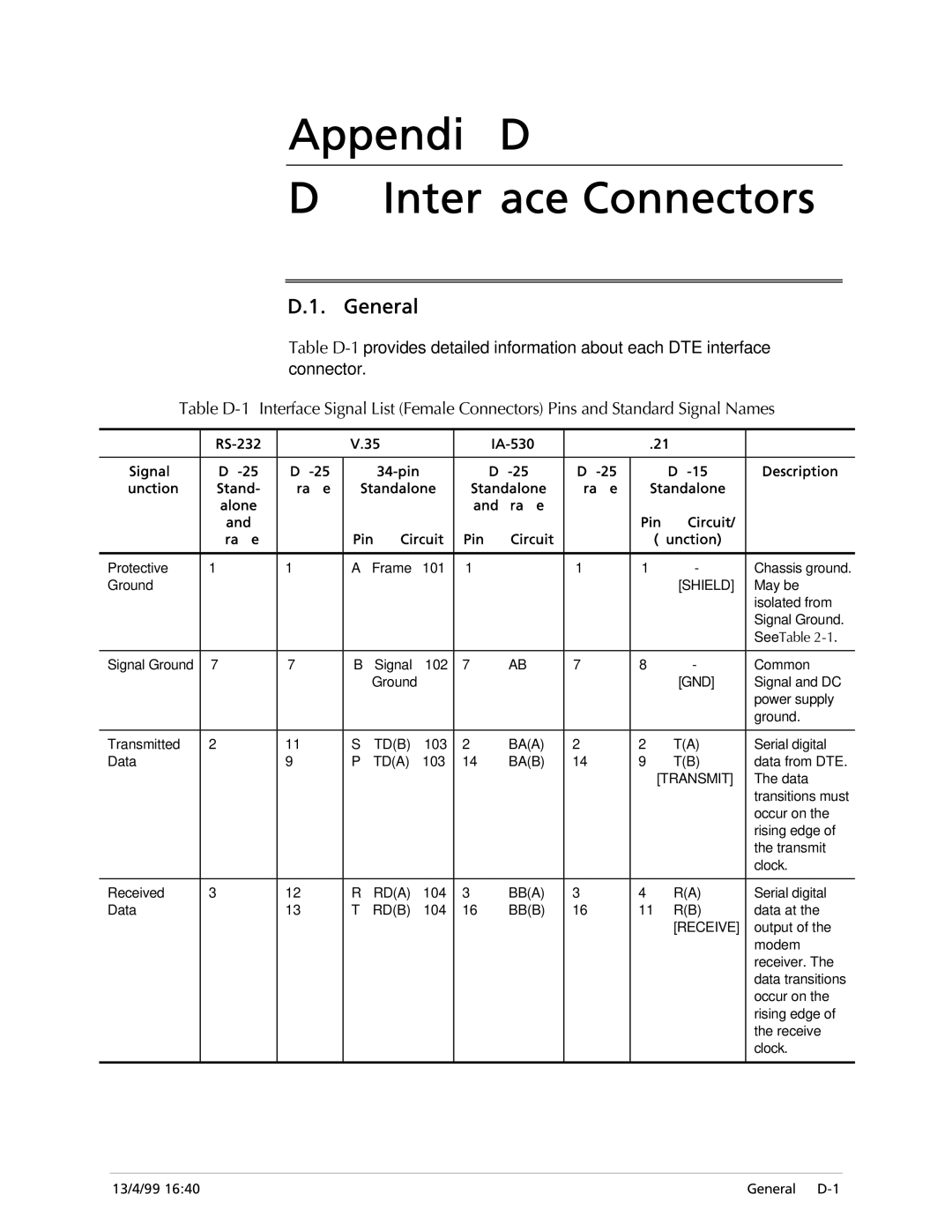
D.1. General
Table
Table
|
| V.35 |
|
| X.21 |
| ||||||
|
|
|
|
|
|
|
|
|
|
|
| |
Signal |
|
|
|
| Description | |||||||
Function | Stand- | Frame | Standalone | Standalone | Frame | Standalone |
| |||||
| alone |
|
|
|
|
| and Frame |
|
|
|
| |
| and |
|
|
|
|
|
|
|
| Pin | Circuit/ |
|
| Frame |
| Pin | Circuit | Pin | Circuit |
| (Function) |
| |||
|
|
|
|
|
|
|
|
|
|
|
| |
Protective | 1 | 1 | A | Frame | 101 | 1 |
| 1 | 1 | - | Chassis ground. | |
Ground |
|
|
|
|
|
|
|
|
|
| [SHIELD] | May be |
|
|
|
|
|
|
|
|
|
|
|
| isolated from |
|
|
|
|
|
|
|
|
|
|
|
| Signal Ground. |
|
|
|
|
|
|
|
|
|
|
|
| See Table |
|
|
|
|
|
|
|
|
|
|
|
| |
Signal Ground | 7 | 7 | B | Signal | 102 | 7 | AB | 7 | 8 | - | Common | |
|
|
|
| Ground |
|
|
|
|
| [GND] | Signal and DC | |
|
|
|
|
|
|
|
|
|
|
|
| power supply |
|
|
|
|
|
|
|
|
|
|
|
| ground. |
|
|
|
|
|
|
|
|
|
|
|
| |
Transmitted | 2 | 11 | S | TD(B) | 103 | 2 | BA(A) | 2 | 2 | T(A) | Serial digital | |
Data |
| 9 | P | TD(A) | 103 | 14 | BA(B) | 14 | 9 | T(B) | data from DTE. | |
|
|
|
|
|
|
|
|
|
| [TRANSMIT] | The data | |
|
|
|
|
|
|
|
|
|
|
|
| transitions must |
|
|
|
|
|
|
|
|
|
|
|
| occur on the |
|
|
|
|
|
|
|
|
|
|
|
| rising edge of |
|
|
|
|
|
|
|
|
|
|
|
| the transmit |
|
|
|
|
|
|
|
|
|
|
|
| clock. |
|
|
|
|
|
|
|
|
|
|
|
| |
Received | 3 | 12 | R | RD(A) | 104 | 3 | BB(A) | 3 | 4 | R(A) | Serial digital | |
Data |
| 13 | T | RD(B) | 104 | 16 | BB(B) | 16 | 11 | R(B) | data at the | |
|
|
|
|
|
|
|
|
|
|
| [RECEIVE] | output of the |
|
|
|
|
|
|
|
|
|
|
|
| modem |
|
|
|
|
|
|
|
|
|
|
|
| receiver. The |
|
|
|
|
|
|
|
|
|
|
|
| data transitions |
|
|
|
|
|
|
|
|
|
|
|
| occur on the |
|
|
|
|
|
|
|
|
|
|
|
| rising edge of |
|
|
|
|
|
|
|
|
|
|
|
| the receive |
|
|
|
|
|
|
|
|
|
|
|
| clock. |
|
|
|
|
|
|
|
|
|
|
|
|
|
13/4/99 16:40 | General |