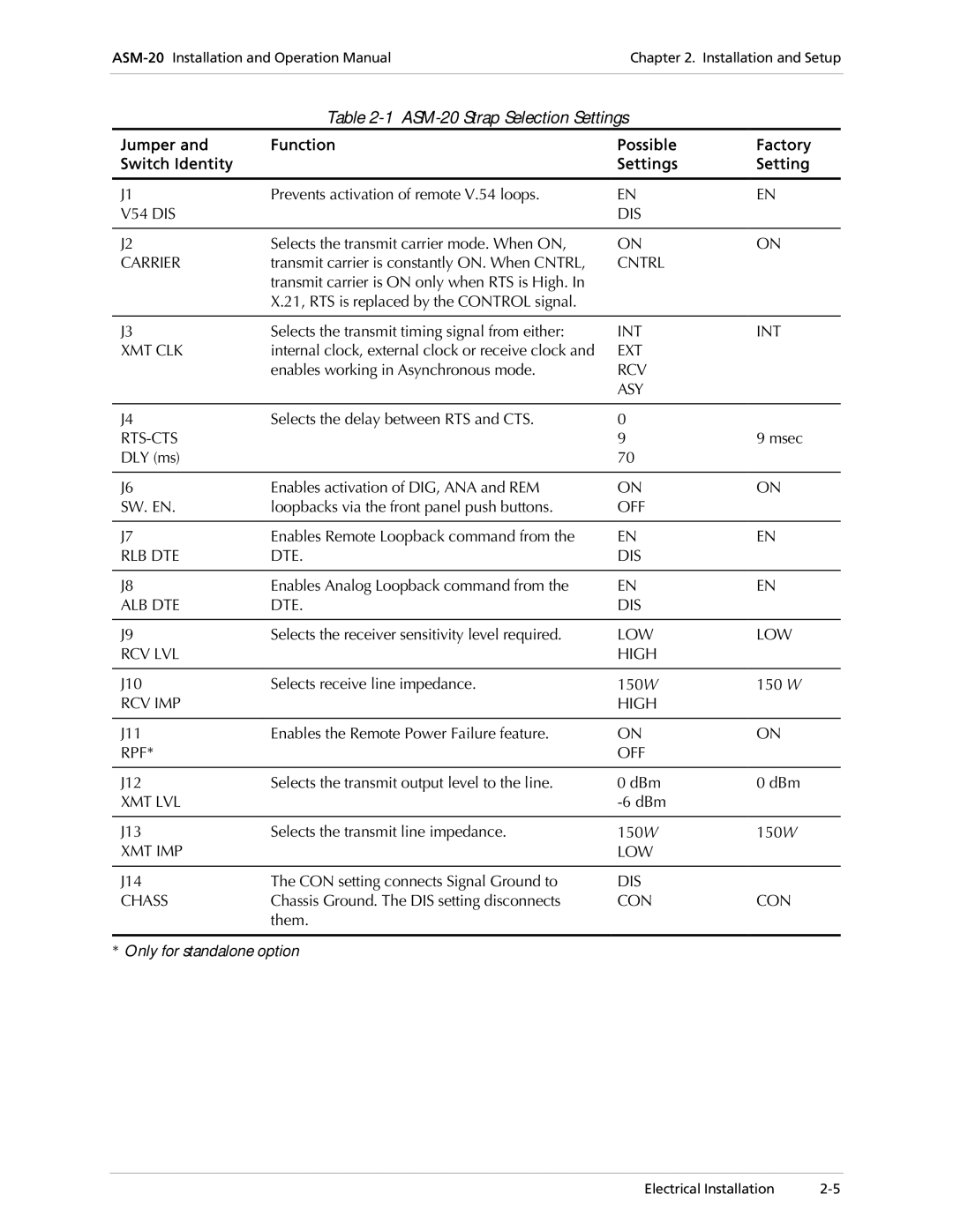
Table 2-1 ASM-20 Strap Selection Settings
Jumper and | Function | Possible | Factory |
Switch Identity |
| Settings | Setting |
|
|
|
|
J1 | Prevents activation of remote V.54 loops. | EN | EN |
V54 DIS |
| DIS |
|
|
|
|
|
J2 | Selects the transmit carrier mode. When ON, | ON | ON |
CARRIER | transmit carrier is constantly ON. When CNTRL, | CNTRL |
|
| transmit carrier is ON only when RTS is High. In |
|
|
| X.21, RTS is replaced by the CONTROL signal. |
|
|
|
|
|
|
J3 | Selects the transmit timing signal from either: | INT | INT |
XMT CLK | internal clock, external clock or receive clock and | EXT |
|
| enables working in Asynchronous mode. | RCV |
|
|
| ASY |
|
|
|
|
|
J4 | Selects the delay between RTS and CTS. | 0 |
|
| 9 | 9 msec | |
DLY (ms) |
| 70 |
|
|
|
|
|
J6 | Enables activation of DIG, ANA and REM | ON | ON |
SW. EN. | loopbacks via the front panel push buttons. | OFF |
|
|
|
|
|
J7 | Enables Remote Loopback command from the | EN | EN |
RLB DTE | DTE. | DIS |
|
|
|
|
|
J8 | Enables Analog Loopback command from the | EN | EN |
ALB DTE | DTE. | DIS |
|
|
|
|
|
J9 | Selects the receiver sensitivity level required. | LOW | LOW |
RCV LVL |
| HIGH |
|
|
|
|
|
J10 | Selects receive line impedance. | 150Ω | 150 Ω |
RCV IMP |
| HIGH |
|
|
|
|
|
J11 | Enables the Remote Power Failure feature. | ON | ON |
RPF* |
| OFF |
|
|
|
|
|
J12 | Selects the transmit output level to the line. | 0 dBm | 0 dBm |
XMT LVL |
|
| |
|
|
|
|
J13 | Selects the transmit line impedance. | 150Ω | 150Ω |
XMT IMP |
| LOW |
|
|
|
|
|
J14 | The CON setting connects Signal Ground to | DIS |
|
CHASS | Chassis Ground. The DIS setting disconnects | CON | CON |
| them. |
|
|
|
|
|
|
*Only for standalone option
Electrical Installation |