Appendix A. Ethernet Interface | ||
|
|
|
|
|
|
|
|
|
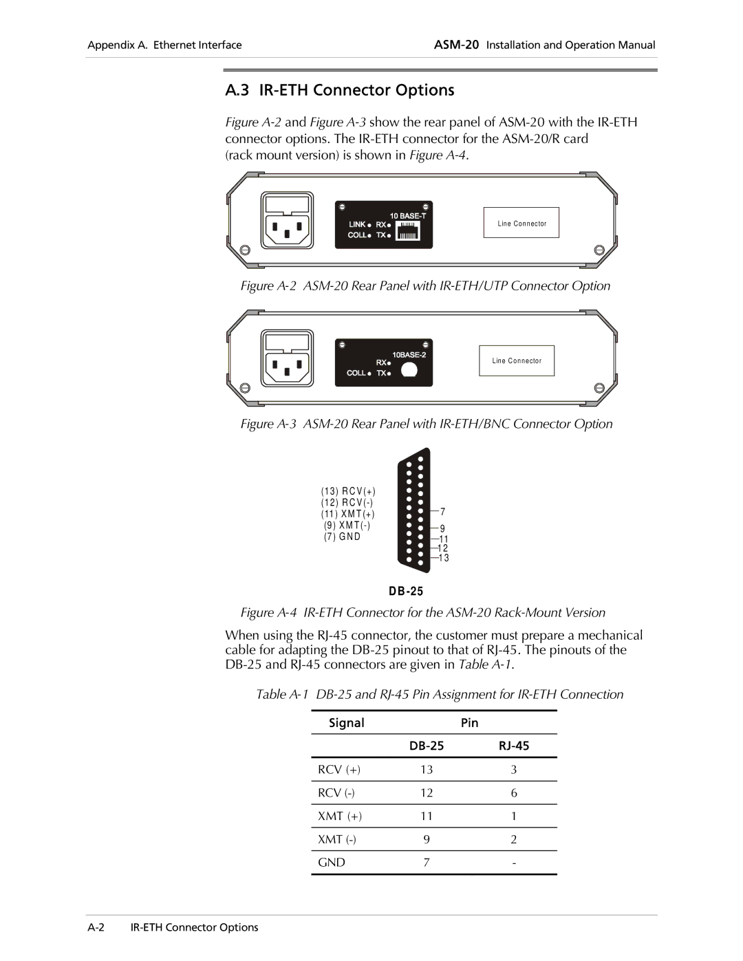
A.3 IR-ETH Connector Options
Figure A-2 and Figure A-3 show the rear panel of ASM-20 with the IR-ETH connector options. The IR-ETH connector for the ASM-20/R card
(rack mount version) is shown in Figure
Line Connector
Figure A-2 ASM-20 Rear Panel with IR-ETH/UTP Connector Option
Line C onnector
Figure A-3 ASM-20 Rear Panel with IR-ETH/BNC Connector Option
(13) R C V (+) |
| |
(12) R C V | 7 | |
(11 ) X M T (+) | ||
(9 ) X M | 9 | |
(7 ) G N D | ||
11 | ||
| 1 2 | |
| 1 3 |
D B
Figure A-4 IR-ETH Connector for the ASM-20 Rack-Mount Version
When using the
Table
Signal |
| Pin |
|
|
|
|
|
|
|
|
|
RCV (+) | 13 | 3 |
|
|
|
RCV | 12 | 6 |
|
|
|
XMT (+) | 11 | 1 |
|
|
|
XMT | 9 | 2 |
|
|
|
GND | 7 | - |
|
|
|