Chapter 4. Troubleshooting and Diagnostics | |
|
|
PATT
P re sse d
P a tte rn
G en e rato r
P a tte rn
Teste r
E rro r
X M T
R C V
A S M
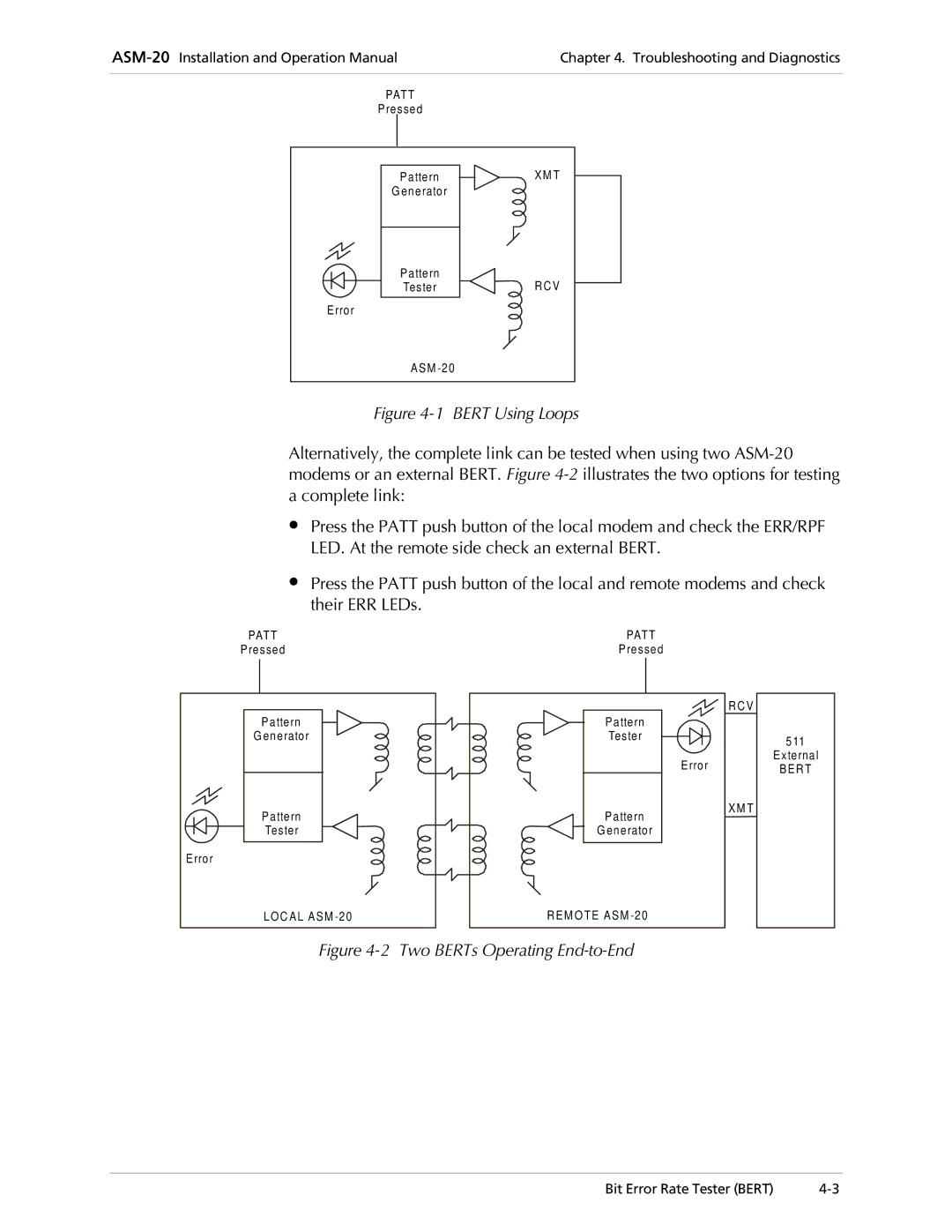
Figure 4-1 BERT Using Loops
Alternatively, the complete link can be tested when using two
∙Press the PATT push button of the local modem and check the ERR/RPF LED. At the remote side check an external BERT.
∙Press the PATT push button of the local and remote modems and check their ERR LEDs.
PATT |
Pressed |
Pattern |
G enerator |
Pattern |
Tester |
Error |
LOC AL ASM |
PATT |
Pressed |
RCV |
Pattern |
Tester |
Error |
XM T |
Pattern |
G enerator |
REM O TE ASM |
511 External
BERT
Figure 4-2 Two BERTs Operating End-to-End
Bit Error Rate Tester (BERT) |