ASM-20 Installation and Operation Manual Chapter 1. Introduction
6/4/99 13:10 Physical Description 1-3
Connection to an RS-449/V.36 interface is accomplished via the RS-530
interface (see Appendix A, Ethernet Interface). ASM-20 incorporates a built-in
Bit Error Rate Tester (BERT). The internal BERT allows complete testing of
both modems and the line without external test equipment. A front panel
switch generates a pseudo-random test pattern (511-bit, according to
ITU/V.52) for testing end-to-end connectivity. The ERROR LED will flash
when a bit error is encountered.
1.2 Physical Description
ASM-20 is available as a desk-top unit or a rack-mountable card for a
19" rack. The rack can carry up to 14 ASM-20 cards which provide a 25-pin
D-type connection to the digital interface. Optional interface adapters for
V.35, X.21, G703 and ETH are available. The ASM-20/R card can detect and
indicate power failure on the remote ASM-20 standalone unit. The RPF LED
will light up if remote power failure occurs.
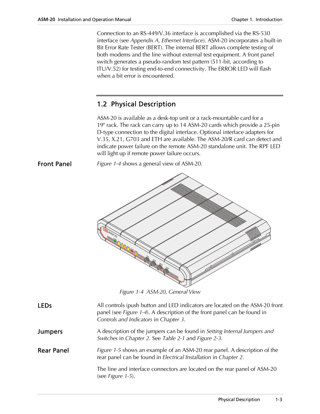
Front Panel Figure 1-4 shows a general view of ASM-20.
Figure 1-4 ASM-20, General View
LEDs All controls (push button and LED indicators are located on the ASM-20 front
panel (see Figure 1-4). A description of the front panel can be found in
Controls and Indicators in Chapter 3.
Jumpers A description of the jumpers can be found in Setting Internal Jumpers and
Switches in Chapter 2. See Table 2-1 and Figure 2-3.
Rear Panel Figure 1-5 shows an example of an ASM-20 rear panel. A description of the
rear panel can be found in Electrical Installation in Chapter 2.
The line and interface connectors are located on the rear panel of ASM-20
(see Figure 1-5).