Chapter 3. Operation | |
|
|
E
P W R |
RT S |
TD |
D C D |
TE S T E R R |
R P F |
D IG |
A N A |
PATT |
ASM - 20 |
1
2
3
4
5
7
A
B
C
D
|
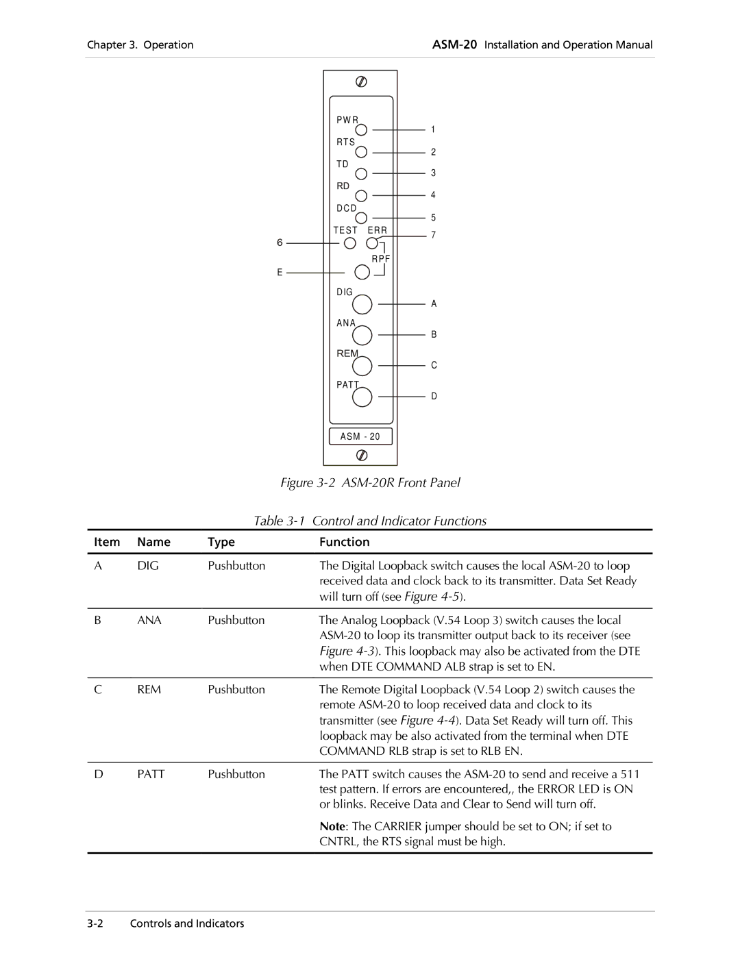
| Figure | |
|
| Table | Control and Indicator Functions |
Item | Name | Type | Function |
|
|
|
|
A | DIG | Pushbutton | The Digital Loopback switch causes the local |
|
|
| received data and clock back to its transmitter. Data Set Ready |
|
|
| will turn off (see Figure |
|
|
|
|
B | ANA | Pushbutton | The Analog Loopback (V.54 Loop 3) switch causes the local |
|
|
| |
|
|
| Figure |
|
|
| when DTE COMMAND ALB strap is set to EN. |
|
|
|
|
C | REM | Pushbutton | The Remote Digital Loopback (V.54 Loop 2) switch causes the |
|
|
| remote |
|
|
| transmitter (see Figure |
|
|
| loopback may be also activated from the terminal when DTE |
|
|
| COMMAND RLB strap is set to RLB EN. |
|
|
|
|
D | PATT | Pushbutton | The PATT switch causes the |
|
|
| test pattern. If errors are encountered,, the ERROR LED is ON |
|
|
| or blinks. Receive Data and Clear to Send will turn off. |
Note: The CARRIER jumper should be set to ON; if set to
CNTRL, the RTS signal must be high.