Chapter 1. Introduction | |
|
|
VAC 50V2T | D T E |
|
| |
|
| X M T | R C V | G N D |
.2A |
|
|
| |
100 |
|
|
| |
~230 V/ ![]() 0.1A T 250V
0.1A T 250V
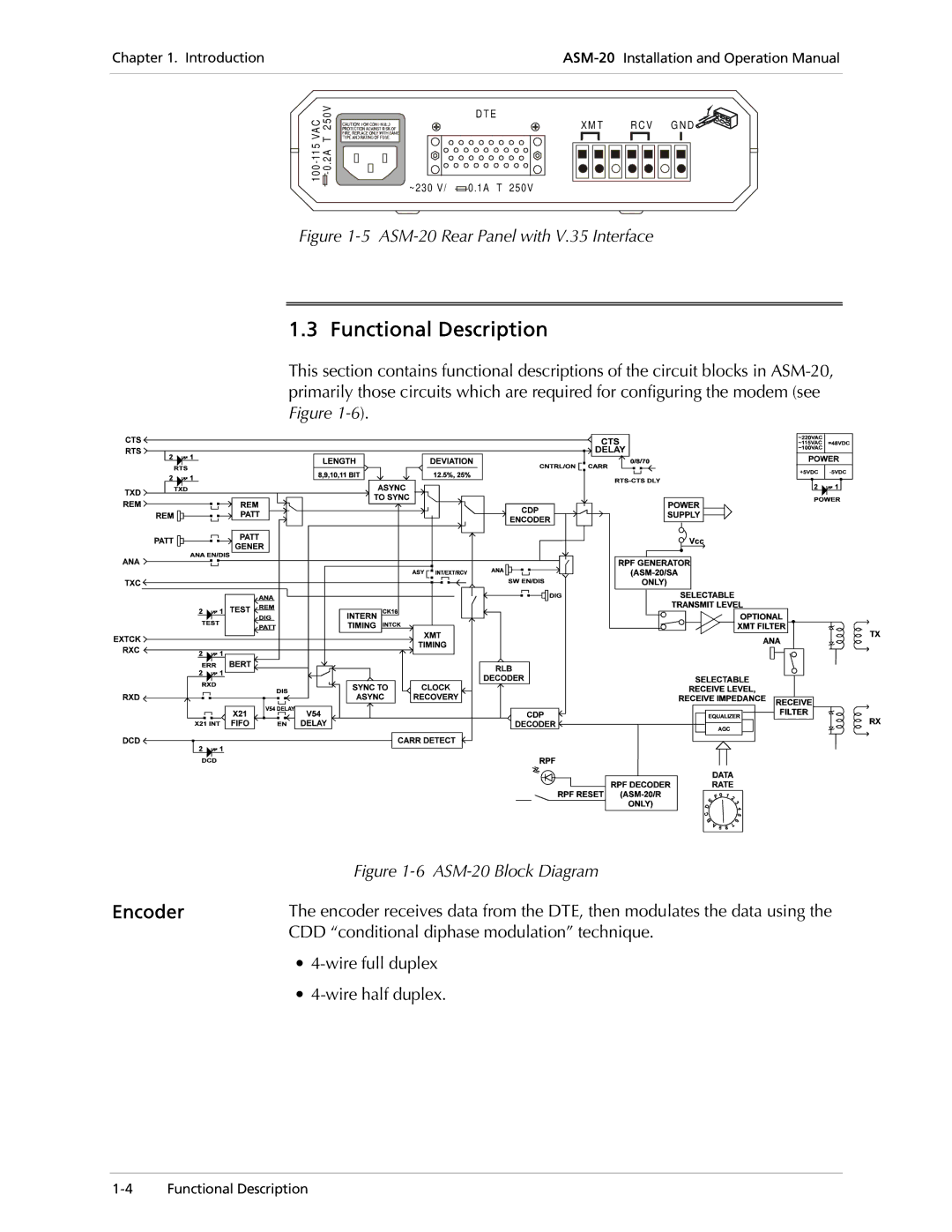
Figure 1-5 ASM-20 Rear Panel with V.35 Interface
1.3 Functional Description
This section contains functional descriptions of the circuit blocks in
| Figure |
Encoder | The encoder receives data from the DTE, then modulates the data using the |
| CDD “conditional diphase modulation” technique. |
∙
∙