Appendix B. | |
|
|
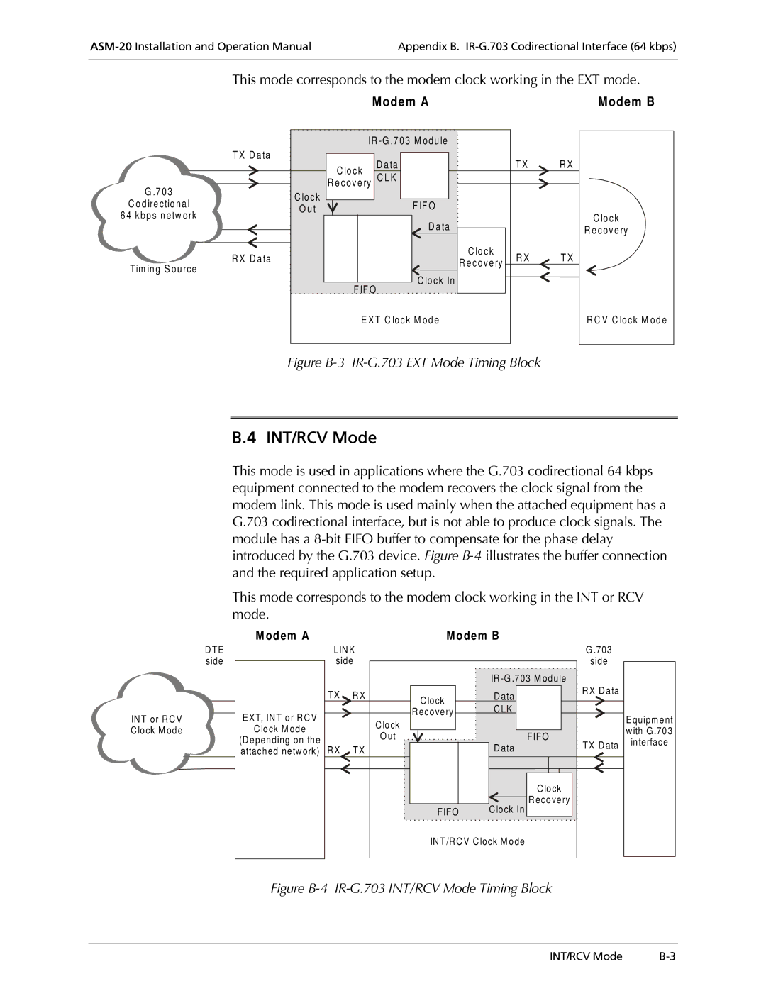
This mode corresponds to the modem clock working in the EXT mode.
Modem A | Modem B |
| IR |
|
|
| |
| T X D a ta | D a ta |
| T X | R X |
| C lo ck |
| |||
| C L K |
|
|
| |
G .7 03 | R e cove ry |
|
|
| |
C lo ck |
|
|
|
| |
C o d ire ctio nal | F IF O |
|
|
| |
O u t |
|
|
| ||
6 4 kbp s n etw ork |
|
|
| C lo ck | |
| D a ta |
|
| ||
|
|
|
| R e cove ry | |
|
|
|
|
| |
| R X D a ta |
| C lo ck | R X | T X |
Tim in g S ou rce |
| R e cove ry | |||
|
|
|
| ||
| C lo ck In |
|
|
| |
| F IF O |
|
|
| |
|
|
|
|
| |
| E X T C lock M od e |
|
| R C V C lock M od e | |
Figure B-3 IR-G.703 EXT Mode Timing Block
B.4 INT/RCV Mode
This mode is used in applications where the G.703 codirectional 64 kbps equipment connected to the modem recovers the clock signal from the modem link. This mode is used mainly when the attached equipment has a G.703 codirectional interface, but is not able to produce clock signals. The module has a
This mode corresponds to the modem clock working in the INT or RCV mode.
INT or RCV Clock M ode
DTE |
side |
M odem A |
|
| M odem B |
| |
| LINK |
|
| G .703 | |
| side |
|
| side | |
|
|
|
| IR |
|
| TX | R X | Clock | Data | RX Data |
|
| ||||
|
|
| CLK |
| |
EXT, INT or RCV |
|
| Recovery |
| |
|
| Clock |
|
| |
Clock M ode |
|
|
|
| |
|
| O ut | FIFO |
| |
(Depending on the |
|
| TX Data | ||
RX | TX |
| Data | ||
attached network) |
| ||||
|
| ||||
|
|
|
| Clock |
|
|
|
|
| Recovery |
|
|
|
| FIFO | Clock In |
|
|
|
| INT/RCV Clock M ode |
| |
Equipment with G .703 interface
Figure B-4 IR-G.703 INT/RCV Mode Timing Block
INT/RCV Mode |