Chapter 4. Troubleshooting and Diagnostics | |
|
|
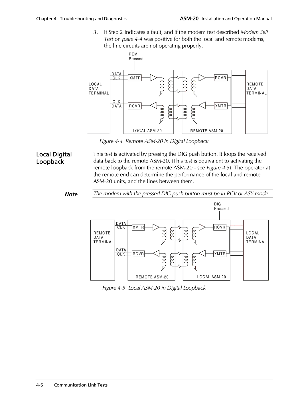
3.If Step 2 indicates a fault, and if the modem test described Modem Self Test on page
L OC A L
D ATA
TE R M IN A L
| REM |
| Pressed |
DATA | X M TR |
CLK | |
CLK |
|
DATA R C V R | |
| LOC AL ASM |
R C V R |
X M TR |
REM O TE ASM |
REM O TE DATA
TE RMINAL
Local Digital Loopback
Figure 4-4 Remote ASM-20 in Digital Loopback
This test is activated by pressing the DIG push button. It loops the received data back to the remote
Note | The modem with the pressed DIG push button must be in RCV or ASY mode |
REM O TE DATA
TE RMINAL
DATA | XM TR |
CLK | |
DATA | RCVR |
CLK | |
| REM O TE ASM |
DIG |
Pressed |
RCVR |
XM TR |
LOC AL ASM |
LOC AL
DATA
TE RMINAL
