Chapter 3
Operation
3.1 General
This chapter:
∙
∙
∙
Describes the controls and indicators of
Explains the operation procedures
Provides jumper and switch information.
Installation procedures given in Chapter 2, Installation and Setup must be completed and checked before attempting to operate the
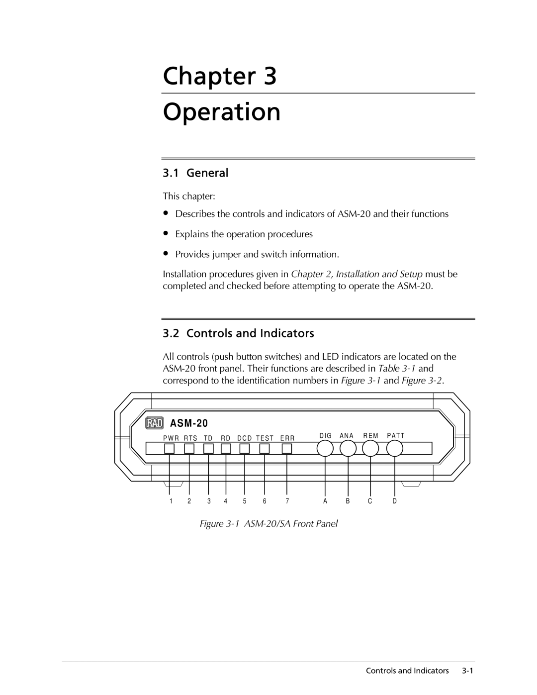
3.2 Controls and Indicators
All controls (push button switches) and LED indicators are located on the
ASM-20
P W R R T S T D R D D C D T E S T E R R D I G A N A R E M P A T T
|
|
|
|
|
|
|
|
|
|
|
|
|
|
|
|
|
|
|
|
|
|
|
|
|
|
|
|
|
|
|
|
|
|
|
|
|
|
|
|
|
|
|
|
|
|
|
|
1 | 2 | 3 |
| 4 | 5 | 6 |
| 7 | A | B | C | D | |||||||||||
Figure 3-1 ASM-20/SA Front Panel
Controls and Indicators