| C.4 |
| The |
| modes which are selectable on the PCB board. The selection is made by |
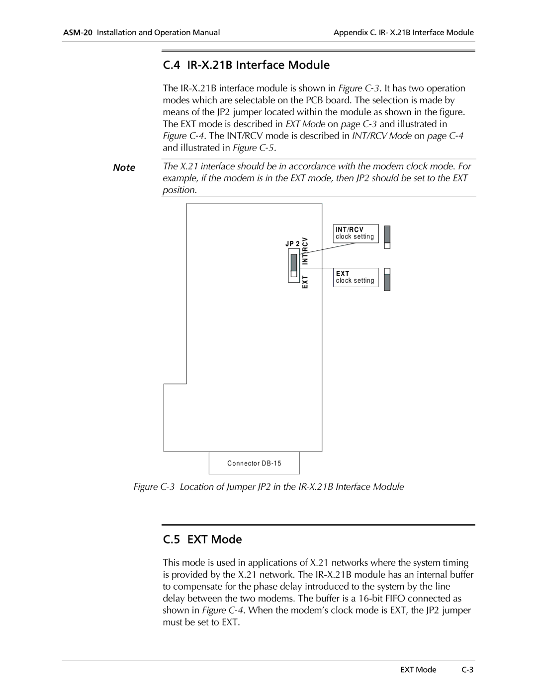
| means of the JP2 jumper located within the module as shown in the figure. |
| The EXT mode is described in EXT Mode on page |
| Figure |
| and illustrated in Figure |
|
|
Note | The X.21 interface should be in accordance with the modem clock mode. For |
| example, if the modem is in the EXT mode, then JP2 should be set to the EXT |
| position. |
|
|
JP 2 | C V | ||
|
|
| IN T/R |
|
|
| |
|
|
| E X T |
|
|
| |
|
|
| |
INT/RCV clock setting
EXT
clock setting
Connector DB
Figure C-3 Location of Jumper JP2 in the IR-X.21B Interface Module
C.5 EXT Mode
This mode is used in applications of X.21 networks where the system timing is provided by the X.21 network. The
EXT Mode |