Appendix D. DTE Interface ConnectorsASM-20Installation & Operation Manual
Table
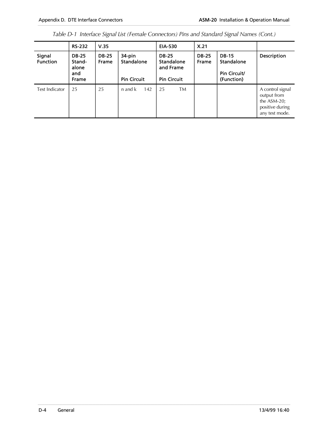
| V.35 |
|
| X.21 |
|
| ||
|
|
|
|
|
|
|
|
|
Signal |
| Description | ||||||
Function | Stand- | Frame | Standalone | Standalone | Frame | Standalone |
| |
| alone |
|
| and Frame |
|
|
| |
| and |
|
|
|
|
| Pin Circuit/ |
|
| Frame |
| Pin Circuit | Pin Circuit |
| (Function) |
| |
|
|
|
|
|
|
|
|
|
Test Indicator | 25 | 25 | n and k 142 | 25 | TM |
|
| A control signal |
|
|
|
|
|
|
|
| output from |
|
|
|
|
|
|
|
| the |
|
|
|
|
|
|
|
| positive during |
|
|
|
|
|
|
|
| any test mode. |
|
|
|
|
|
|
|
|
|
General | 13/4/99 16:40 |