61200375L1-1 TA 850
T1 RCU VoATM UIG/61200376L2-31A Page 50 of 72
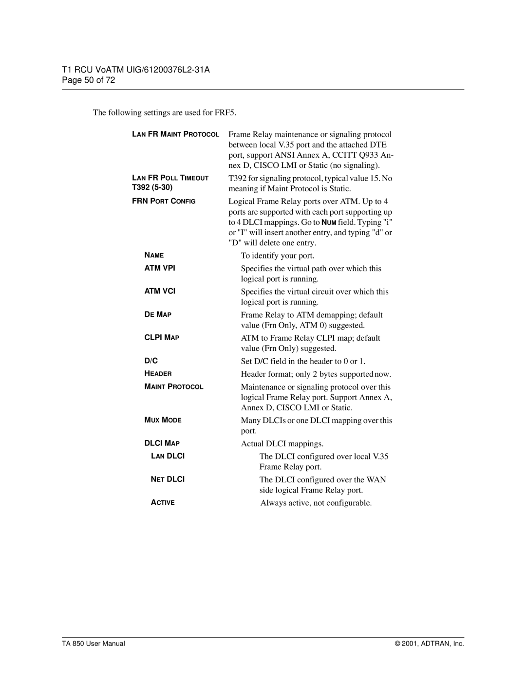
The following settings are used for FRF5.
LAN FR MAINT PROTOCOL
LAN FR POLL TIMEOUT
T392
FRN PORT CONFIG
NAME
ATM VPI
ATM VCI
DE MAP
CLPI MAP
D/C
HEADER
MAINT PROTOCOL
MUX MODE
DLCI MAP
LAN DLCI
NET DLCI
ACTIVE
Frame Relay maintenance or signaling protocol between local V.35 port and the attached DTE port, support ANSI Annex A, CCITT Q933 An- nex D, CISCO LMI or Static (no signaling).
T392 for signaling protocol, typical value 15. No meaning if Maint Protocol is Static.
Logical Frame Relay ports over ATM. Up to 4 ports are supported with each port supporting up to 4 DLCI mappings. Go to NUM field. Typing "i" or "I" will insert another entry, and typing "d" or "D" will delete one entry.
To identify your port.
Specifies the virtual path over which this logical port is running.
Specifies the virtual circuit over which this logical port is running.
Frame Relay to ATM demapping; default value (Frn Only, ATM 0) suggested.
ATM to Frame Relay CLPI map; default value (Frn Only) suggested.
Set D/C field in the header to 0 or 1.
Header format; only 2 bytes supported now.
Maintenance or signaling protocol over this logical Frame Relay port. Support Annex A, Annex D, CISCO LMI or Static.
Many DLCIs or one DLCI mapping over this port.
Actual DLCI mappings.
The DLCI configured over local V.35 Frame Relay port.
The DLCI configured over the WAN side logical Frame Relay port.
Always active, not configurable.
TA 850 User Manual | © 2001, ADTRAN, Inc. |
