Planning and designating a Main Distribution Frame Page 135 of 456
Procedure 11
Installing the BIX cross-connect terminal
1Refer to the equipment layout plan to determine where to place the
2Lay out the terminal blocks as shown in Figure 50 on page 137.
3Attach labels on the
•
•AUX wiring
•Power Failure Transfer Units (PFTU)
•Telephones and consoles
•Trunks
•Miscellaneous equipment
End of Procedure
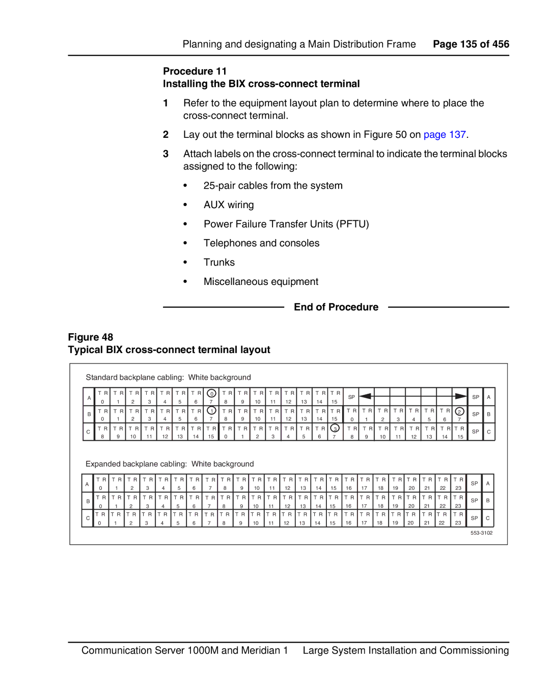
Figure 48
Typical BIX cross-connect terminal layout
Standard backplane cabling: White background |
|
|
|
|
|
|
|
|
|
|
|
|
|
|
|
| |||||||||||
A | T R T R T R T R T R T R T R 0 | T R T R T R T R T R T R T R T R | SP |
|
|
|
|
|
|
| SP | A | |||||||||||||||
0 | 1 | 2 | 3 | 4 | 5 | 6 | 7 | 8 | 9 | 10 | 11 | 12 | 13 | 14 | 15 |
|
|
|
|
|
|
| |||||
|
|
|
|
|
|
|
|
|
|
| |||||||||||||||||
B | T R T R T R T R T R T R T R 1 | T R T R T R T R T R T R T R T R T R T R T R T R T R T R T R | 2 | SP | B | ||||||||||||||||||||||
0 | 1 | 2 | 3 | 4 | 5 | 6 | 7 | 8 | 9 | 10 | 11 | 12 | 13 | 14 | 15 | 0 | 1 | 2 | 3 | 4 | 5 | 6 | 7 | ||||
|
|
| |||||||||||||||||||||||||
C | T R T R T R T R T R T R T R T R | T R T R T R T R T R T R T R 3 | T R T R T R T R T R T R T R | T R | SP | C | |||||||||||||||||||||
8 | 9 | 10 | 11 | 12 | 13 | 14 | 15 | 0 | 1 | 2 | 3 | 4 | 5 | 6 | 7 | 8 | 9 | 10 | 11 | 12 | 13 | 14 | 15 | ||||
|
|
| |||||||||||||||||||||||||
Expanded backplane cabling: White background |
|
|
|
|
|
|
|
|
|
|
|
|
|
|
| ||||||||||||
A | T R T R T R T R T R T R T R T R | T R T R T R T R T R T R T R T R T R T R T R T R T R T R T R T R | SP | A | |||||||||||||||||||||||
0 | 1 | 2 | 3 | 4 | 5 | 6 | 7 | 8 | 9 | 10 | 11 | 12 | 13 | 14 | 15 | 16 | 17 | 18 | 19 | 20 | 21 | 22 | 23 | ||||
|
|
| |||||||||||||||||||||||||
B | T R T R T R T R T R T R T R | T R | T R T R T R T R T R T R T R T R T R T R T R T R T R T R T R T R | SP | B | ||||||||||||||||||||||
0 | 1 | 2 | 3 | 4 | 5 | 6 | 7 | 8 | 9 | 10 | 11 | 12 | 13 | 14 | 15 | 16 | 17 | 18 | 19 | 20 | 21 | 22 | 23 | ||||
|
|
| |||||||||||||||||||||||||
C | T R T R T R T R T R T R T R | T R | T R T R T R T R T R T R T R T R T R T R T R T R T R T R T R T R | SP | C | ||||||||||||||||||||||
0 | 1 | 2 | 3 | 4 | 5 | 6 | 7 | 8 | 9 | 10 | 11 | 12 | 13 | 14 | 15 | 16 | 17 | 18 | 19 | 20 | 21 | 22 | 23 | ||||
|
|
| |||||||||||||||||||||||||
|
|
|
|
|
|
|
|
|
|
|
|
|
|
|
|
|
|
|
|
|
|
|
|
| |||
Communication Server 1000M and Meridian 1 Large System Installation and Commissioning