Cabling Common Equipment in a Single Group system Page 203 of 456
Optioning the System Utility Card
To install the system utility card, first identify Core/Net 0 and Core/Net 1 shelves. Then adjust the DIP switches according to Table 25.
Table 25
System Utility Card DIP switch settings
| Core/Net 0 | Core/Net 1 |
|
|
|
DIP switch 1 | on | off |
|
|
|
DIP switch 2 | on | on |
|
|
|
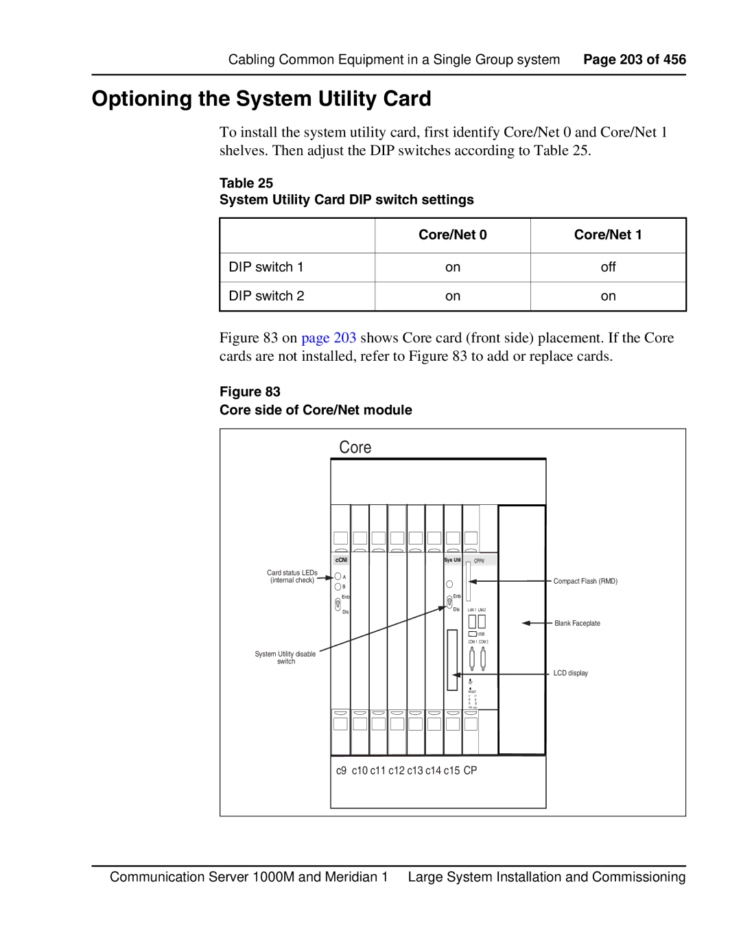
Figure 83 on page 203 shows Core card (front side) placement. If the Core cards are not installed, refer to Figure 83 to add or replace cards.
Figure 83
Core side of Core/Net module
| Core |
|
|
|
|
| cCNI | Sys Util | CPPIV |
| |
Card status LEDs | A |
|
|
|
|
(internal check) |
|
|
| Compact Flash (RMD) | |
B |
|
|
| ||
|
|
|
|
| |
| Enb | Enb |
|
|
|
| Dis | Dis | LAN 1 | LAN 2 |
|
|
|
|
|
| |
|
|
| L |
| Blank Faceplate |
|
|
|
|
| |
|
|
| LUSB |
| |
|
|
| COM 1 COM 2 |
| |
System Utility disable |
|
| C |
|
|
switch |
|
|
|
| |
|
|
|
|
| |
|
|
|
| U | LCD display |
|
|
| INIT |
|
|
|
|
| RESET |
|
|
|
|
| CF CF |
|
|
|
|
| PWR HDD |
|
|
| c9 c10 c11 c12 c13 c14 c15 CP |
|
| ||
Communication Server 1000M and Meridian 1 Large System Installation and Commissioning