Page 268 of 456 Cabling lines and trunks
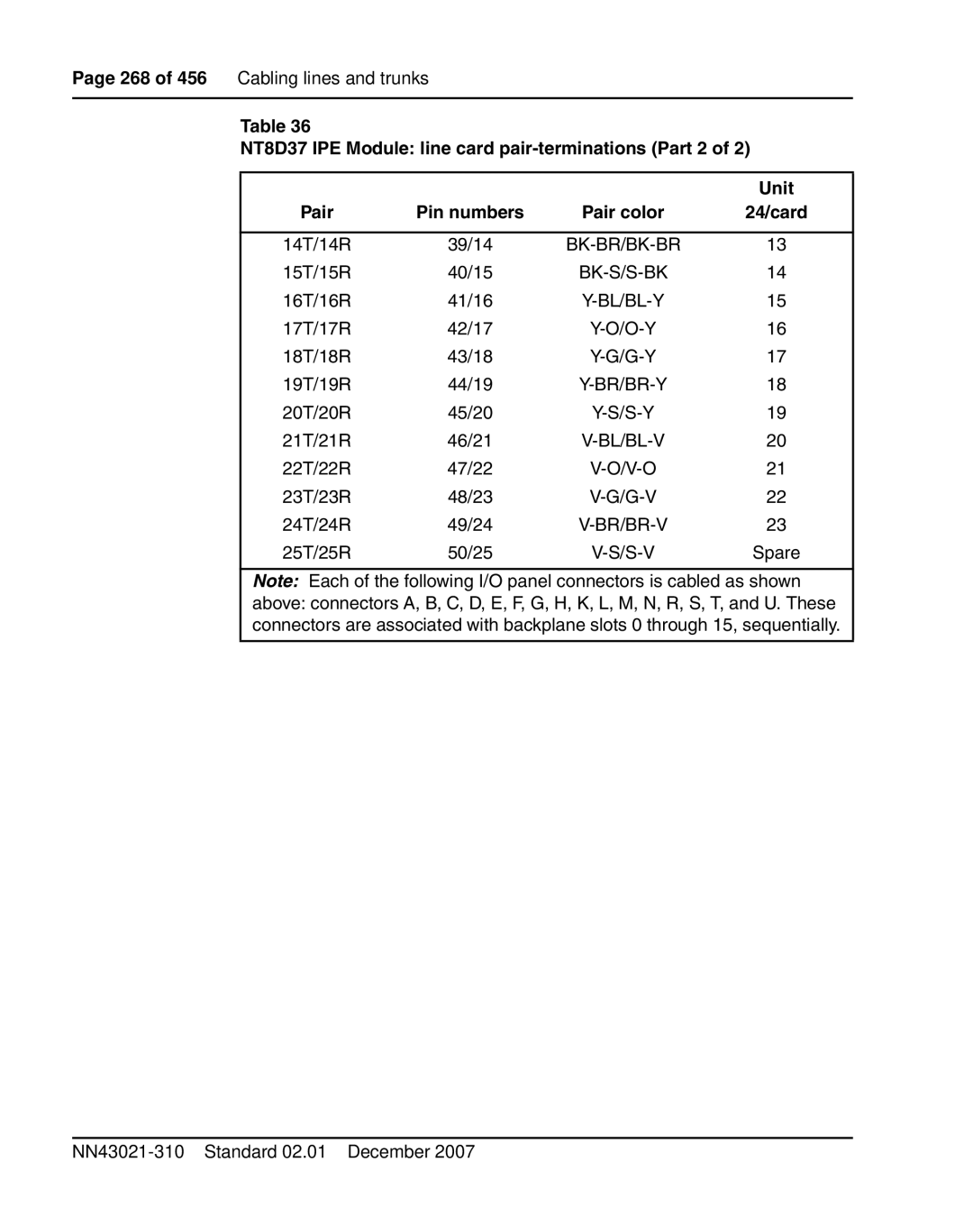
Table 36
NT8D37 IPE Module: line card pair-terminations (Part 2 of 2)
|
|
| Unit |
Pair | Pin numbers | Pair color | 24/card |
|
|
|
|
14T/14R | 39/14 | 13 | |
15T/15R | 40/15 | 14 | |
16T/16R | 41/16 | 15 | |
17T/17R | 42/17 | 16 | |
18T/18R | 43/18 | 17 | |
19T/19R | 44/19 | 18 | |
20T/20R | 45/20 | 19 | |
21T/21R | 46/21 | 20 | |
22T/22R | 47/22 | 21 | |
23T/23R | 48/23 | 22 | |
24T/24R | 49/24 |
| 23 |
25T/25R | 50/25 |
| Spare |
Note: Each of the following I/O panel connectors is cabled as shown
above: connectors A, B, C, D, E, F, G, H, K, L, M, N, R, S, T, and U. These connectors are associated with backplane slots 0 through 15, sequentially.
