Page 56 of 456 Preparing for installation
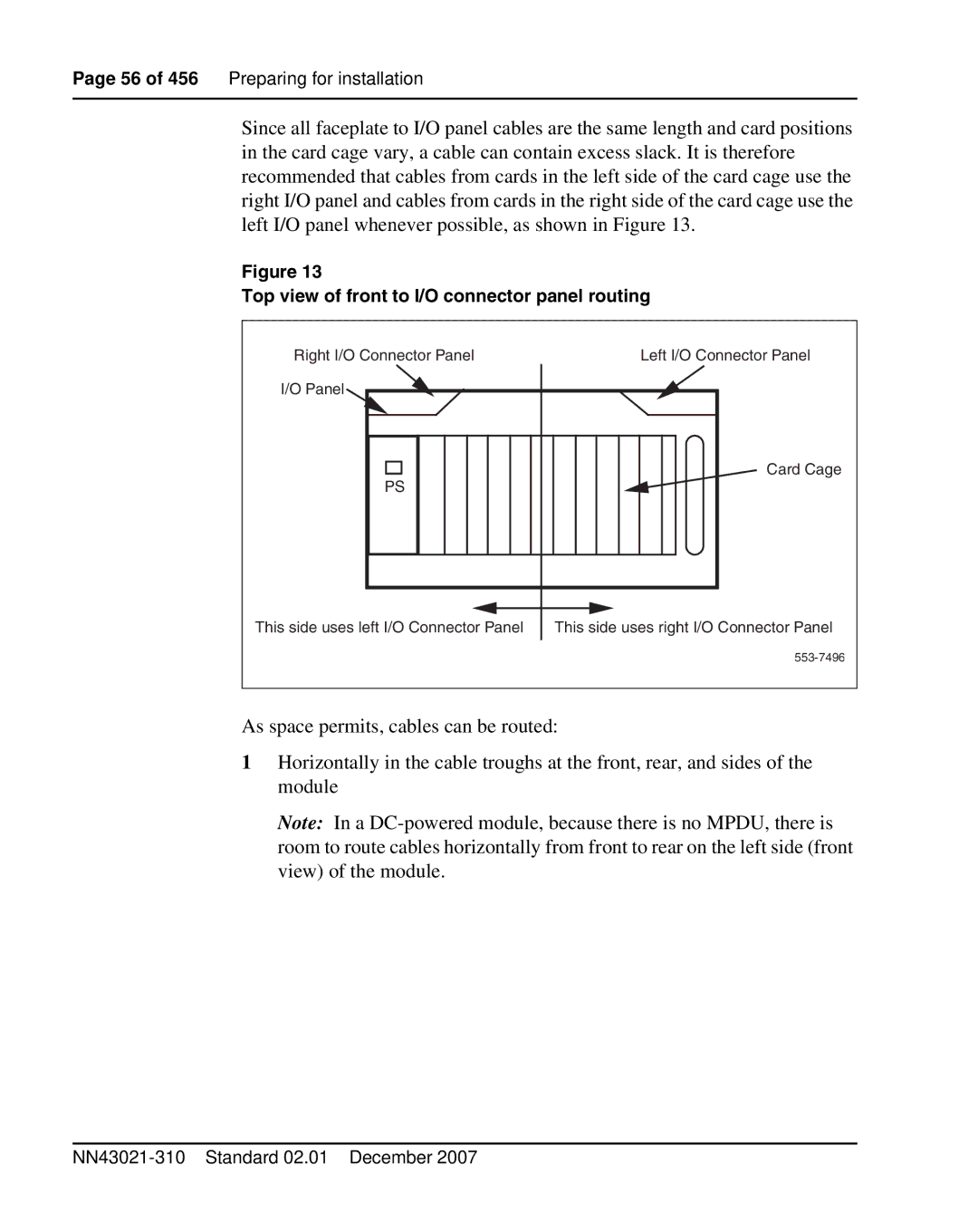
Since all faceplate to I/O panel cables are the same length and card positions in the card cage vary, a cable can contain excess slack. It is therefore recommended that cables from cards in the left side of the card cage use the right I/O panel and cables from cards in the right side of the card cage use the left I/O panel whenever possible, as shown in Figure 13.
Figure 13
Top view of front to I/O connector panel routing
Right I/O Connector Panel I/O Panel![]()
![]()
PS |
Left I/O Connector Panel
Card Cage
This side uses left I/O Connector Panel | This side uses right I/O Connector Panel |
As space permits, cables can be routed:
1Horizontally in the cable troughs at the front, rear, and sides of the module
Note: In a