Page 152 of 456 Configuring the system monitor
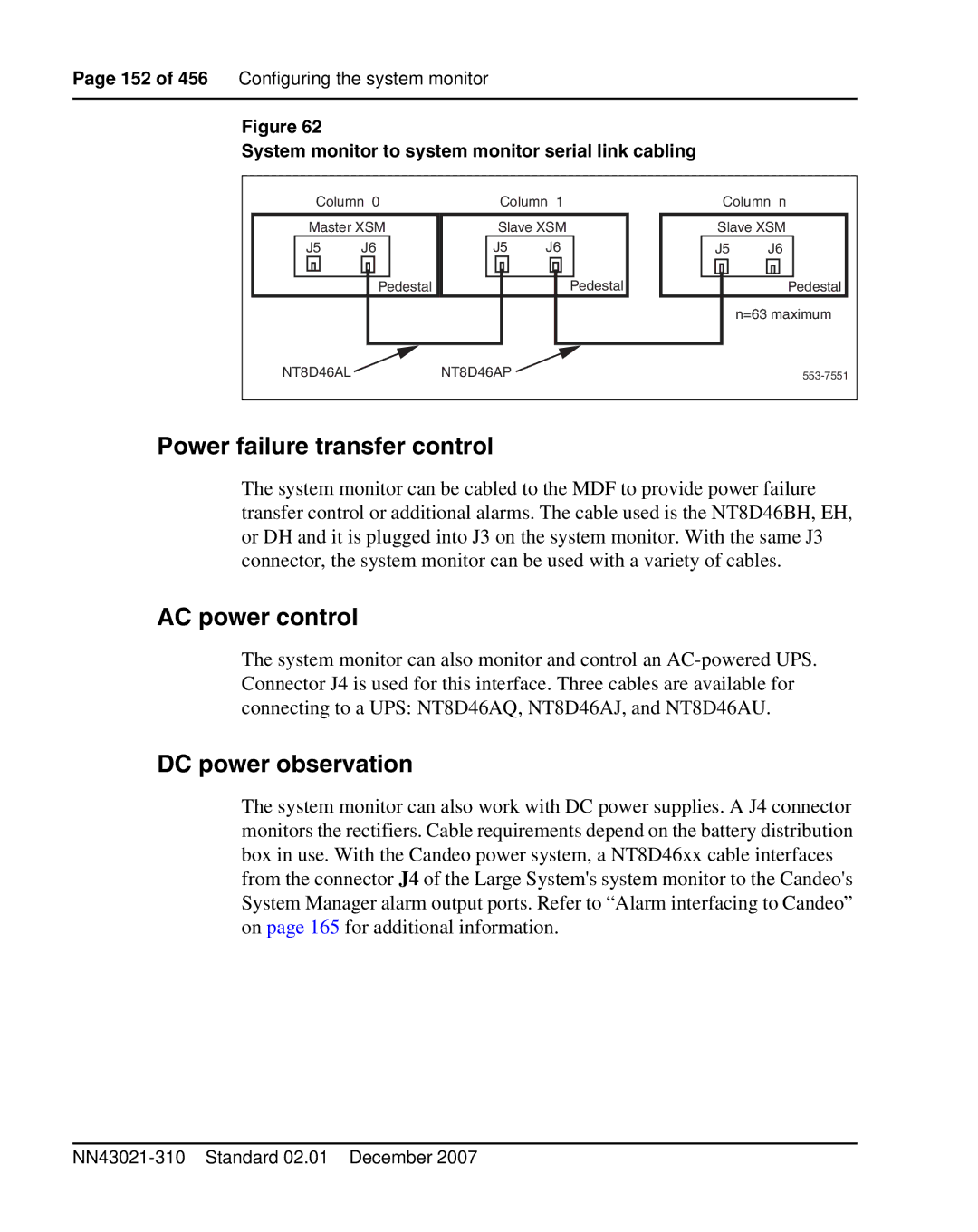
Figure 62
System monitor to system monitor serial link cabling
Column 0 | Column 1 | Column n | |||
Master XSM | Slave XSM | Slave XSM | |||
J5 | J6 | J5 | J6 | J5 | J6 |
| Pedestal |
| Pedestal |
| Pedestal |
|
|
|
|
| n=63 maximum |
NT8D46AL |
| NT8D46AP |
|
| |
Power failure transfer control
The system monitor can be cabled to the MDF to provide power failure transfer control or additional alarms. The cable used is the NT8D46BH, EH, or DH and it is plugged into J3 on the system monitor. With the same J3 connector, the system monitor can be used with a variety of cables.
AC power control
The system monitor can also monitor and control an
DC power observation
The system monitor can also work with DC power supplies. A J4 connector
monitors the rectifiers. Cable requirements depend on the battery distribution box in use. With the Candeo power system, a NT8D46xx cable interfaces from the connector J4 of the Large System's system monitor to the Candeo's System Manager alarm output ports. Refer to “Alarm interfacing to Candeo” on page 165 for additional information.