Installing earthquake bracing Page 353 of 456
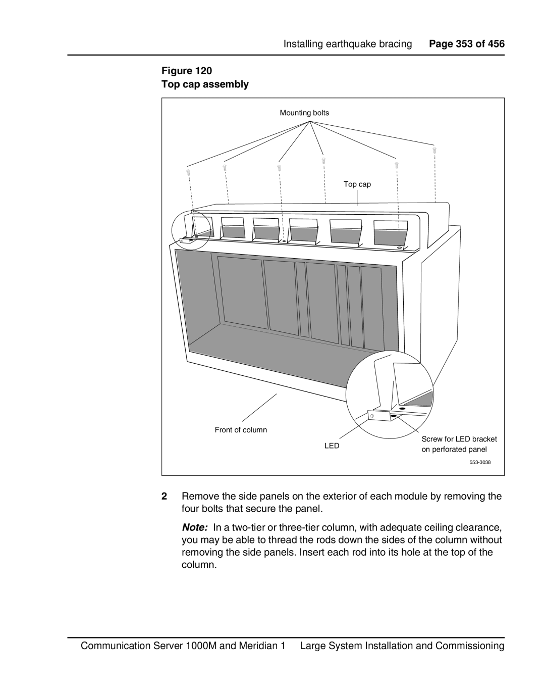
Figure 120
Top cap assembly
Mounting bolts |
| |
| Top cap | |
Front of column |
| |
LED | Screw for LED bracket | |
on perforated panel | ||
| ||
|
2Remove the side panels on the exterior of each module by removing the four bolts that secure the panel.
Note: In a
Communication Server 1000M and Meridian 1 Large System Installation and Commissioning
