Planning and designating a Main Distribution Frame Page 137 of 456
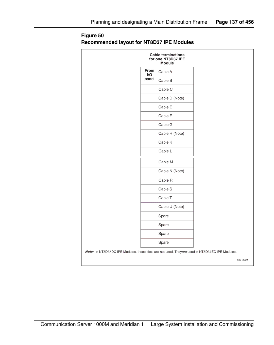
Figure 50
Recommended layout for NT8D37 IPE Modules
Cable terminations for one NT8D37 IPE Module
From Cable A
I/O
panel Cable B
Cable C
Cable D (Note)
Cable E
Cable F
Cable G
Cable H (Note)
Cable K
Cable L
Cable M
Cable N (Note)
Cable K
Cable R
Cable S
Cable T
Cable U (Note)
Spare
Spare
Spare
Spare
Note: In NT8D37DC IPE Modules, these slots are not used. Theyare used in NT8D37EC IPE Modules.
Communication Server 1000M and Meridian 1 Large System Installation and Commissioning