Placing the fourth module on a column Page 69 of 456
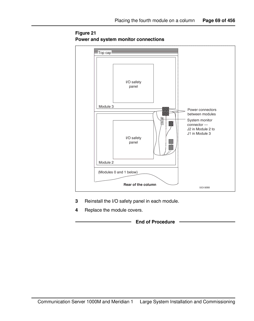
Figure 21
Power and system monitor connections
![]() Top cap
Top cap
I/O safety
panel
Module 3
I/O safety |
panel |
Module 2 |
Power connectors between modules
System monitor connector —
J2 in Module 2 to
J1 in Module 3
(Modules 0 and 1 below)
Rear of the column
3Reinstall the I/O safety panel in each module.
4Replace the module covers.
End of Procedure
Communication Server 1000M and Meridian 1 Large System Installation and Commissioning
