Page 114 of 456 Installing DC power
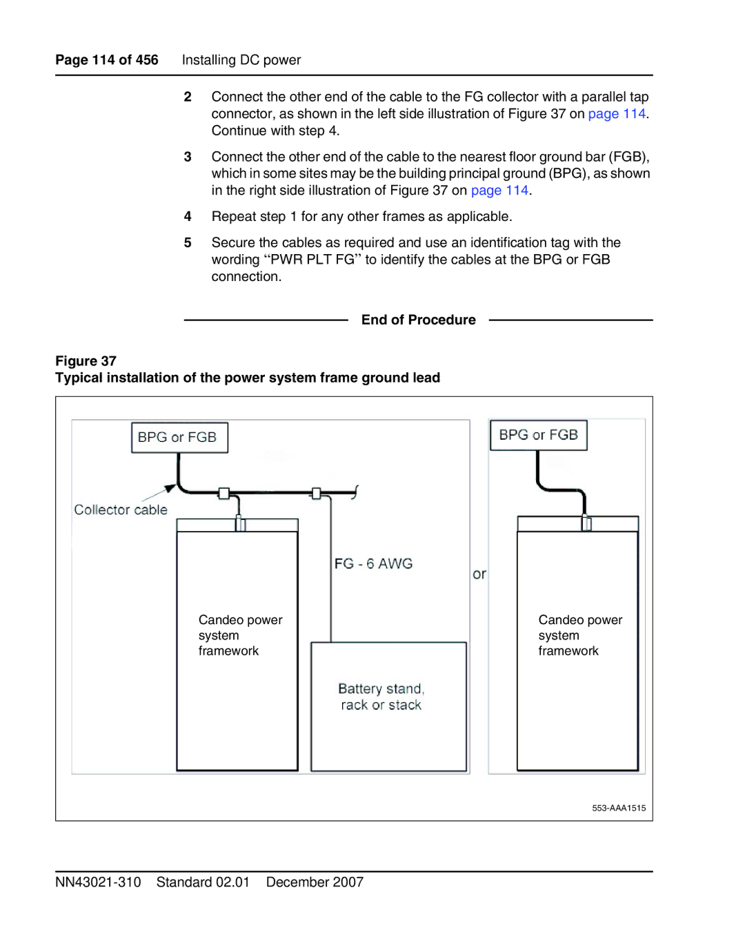
2Connect the other end of the cable to the FG collector with a parallel tap connector, as shown in the left side illustration of Figure 37 on page 114. Continue with step 4.
3Connect the other end of the cable to the nearest floor ground bar (FGB), which in some sites may be the building principal ground (BPG), as shown in the right side illustration of Figure 37 on page 114.
4Repeat step 1 for any other frames as applicable.
5Secure the cables as required and use an identification tag with the wording “PWR PLT FG” to identify the cables at the BPG or FGB connection.
End of Procedure
Figure 37
Typical installation of the power system frame ground lead
Candeo power system framework
Candeo power system framework