Page 148 of 456 Installing Power Failure Transfer Units
Installing a PFTU
Use the following procedure and any instructions provided with the Power Failure Transfer Unit (PFTU) to install and connect PFTUs.
Procedure 13
Installing a PFTU
1Install a PFTU according to the manufacturer’s instructions.
2Attach the yellow PFTU label to the designation strip, indicating the top connector as P1 and the bottom connector as P2.
3Install two
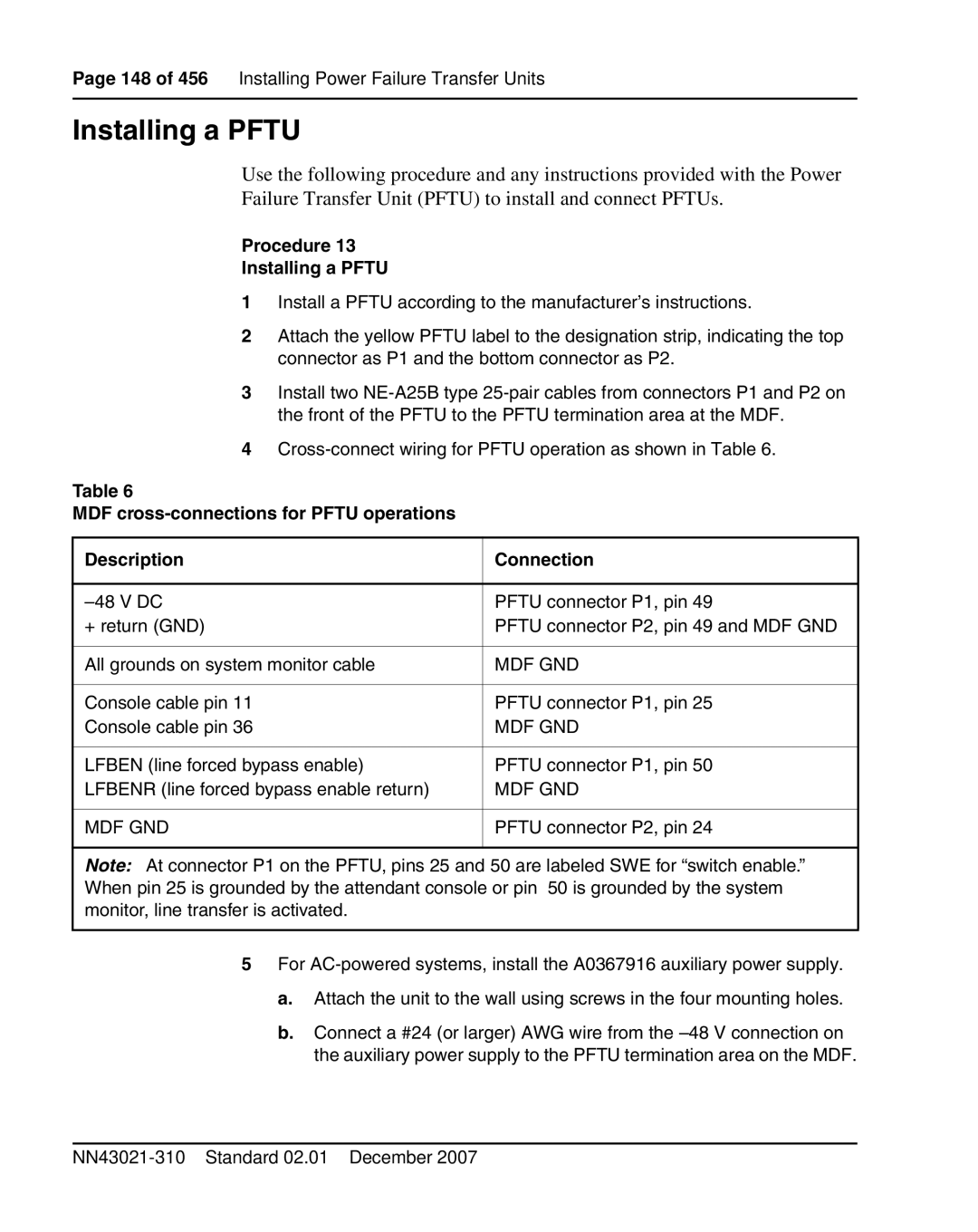
4
Table 6
MDF
Description | Connection |
|
|
PFTU connector P1, pin 49 | |
+ return (GND) | PFTU connector P2, pin 49 and MDF GND |
|
|
All grounds on system monitor cable | MDF GND |
|
|
Console cable pin 11 | PFTU connector P1, pin 25 |
Console cable pin 36 | MDF GND |
|
|
LFBEN (line forced bypass enable) | PFTU connector P1, pin 50 |
LFBENR (line forced bypass enable return) | MDF GND |
|
|
MDF GND | PFTU connector P2, pin 24 |
|
|
Note: At connector P1 on the PFTU, pins 25 and 50 are labeled SWE for “switch enable.” When pin 25 is grounded by the attendant console or pin 50 is grounded by the system monitor, line transfer is activated.
5For
a.Attach the unit to the wall using screws in the four mounting holes.
b.Connect a #24 (or larger) AWG wire from the
