Page 124 of 456 Installing DC power
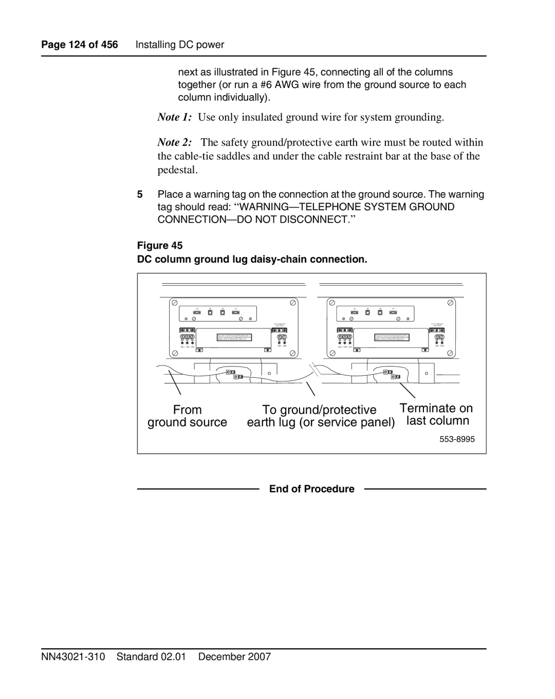
next as illustrated in Figure 45, connecting all of the columns together (or run a #6 AWG wire from the ground source to each column individually).
Note 1: Use only insulated ground wire for system grounding.
Note 2: The safety ground/protective earth wire must be routed within the
5Place a warning tag on the connection at the ground source. The warning tag should read:
Figure 45
DC column ground lug
J3 | J5 | J6 | J4 |
FLTR / PWR DIST
UNIT ASSY
+ + LRTN
![]()
![]() EACH INPUT CIRCUIT MUST BE PROVIDED WITH A
EACH INPUT CIRCUIT MUST BE PROVIDED WITH A
LISTED FUSE OR CIRCUIT BREAKER SUITABLE FOR
![]() BRANCH CIRCUIT PROTECTION, RATED 30A.
BRANCH CIRCUIT PROTECTION, RATED 30A. ![]()
J3 | J5 | J6 | J4 |
FLTR / PWR DIST
UNIT ASSY
+ + LRTN
![]()
![]() EACH INPUT CIRCUIT MUST BE PROVIDED WITH A
EACH INPUT CIRCUIT MUST BE PROVIDED WITH A
LISTED FUSE OR CIRCUIT BREAKER SUITABLE FOR
![]() BRANCH CIRCUIT PROTECTION, RATED 30A.
BRANCH CIRCUIT PROTECTION, RATED 30A. ![]()
BLO CB0 CB1
CB2 CB3 | BLO CB0 CB1 | CB2 CB3 |
From | To ground/protective | Terminate on |
ground source | earth lug (or service panel) | last column |
|
| |
| End of Procedure |
|