Page 146 of 456 Installing Power Failure Transfer Units
5Designated telephones (DTMF or rotary dial types)
6Central office trunks
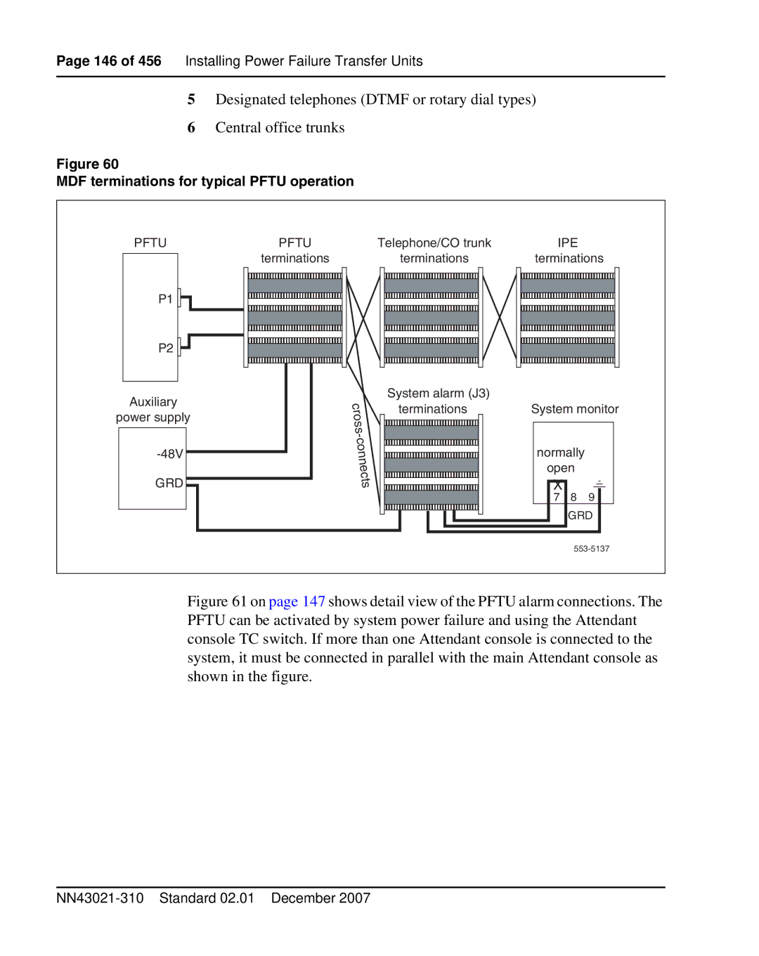
Figure 60
MDF terminations for typical PFTU operation
PFTU | PFTU | Telephone/CO trunk | IPE |
| |
| terminations | terminations | terminations | ||
P1 |
|
|
|
|
|
P2 |
|
|
|
|
|
Auxiliary |
| System alarm (J3) |
|
|
|
| terminations | System monitor | |||
power supply |
| ||||
|
|
|
|
| |
|
| normally |
| ||
|
|
| open |
| |
GRD |
|
| X |
|
|
|
|
| 7 | 8 | 9 |
|
|
|
| GRD | |
|
|
|
| ||